 |
Interior cut outs should always have radiused
corners. They look better and are stronger than sharp corners. I use a 1/2" sanding
drum on a Dremel to make the corners.
First mark the center of the corners and drill
a hole smaller than the finished radius. I normally use a 3/8" bit
in a drill press to get started.
Next, use a hobby knife, scroll saw or
jeweler's saw to finish the cut-out.
Finally sand the inside to smooth it out
and use a Dremel or a dowel with sandpaper wrapped around it to finish the
corner.
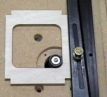
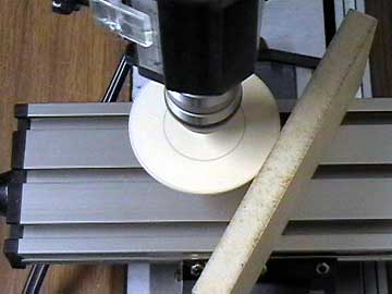
Here I am showing my anal-retentive nature
by using a sanding drum on my Dremel in my
router table to clean up the inside cut-out.
|
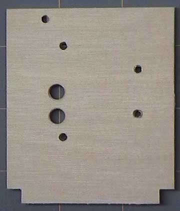 |
The front face of the
firewall. It has
been drilled for the
engine mount, fuel lines and
throttle linkage.
This aircraft will have a
tail wheel so there is no
nose gear mount.
Notice that the
fuel line holes have been
chamfered using a counter-sink to soften the edge and help prevent the
plywood from cutting the fuel line. |
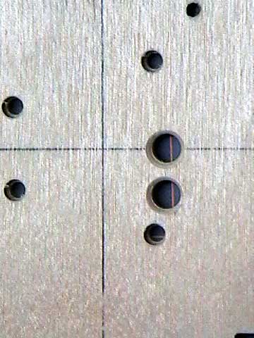 |
The rear face of the firewall. Again,
notice the chamfered fuel line holes.
Also note that the holes for the engine mount
screws have been enlarged slightly on the rear face to receive the blind
nuts. |
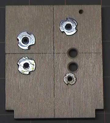 |
The blind nuts have been
tapped in place with a small hammer. The smaller blind nut is made
by a different manufacturer but they all have the same thread (6-32).
I used a small blind nut so
that I would not have to grind away part of the flange to prevent it
from blocking the fuel line holes. However, if you run into this
problem you can grind away part of the flange with a Dremel. The
blind nut will still be strong enough.
|
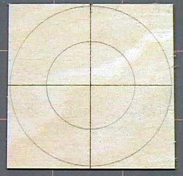 |
It is easy to make a perfect nose ring.
Start by selecting a piece of plywood of appropriate thickness.
Draw the centerlines and the outer diameter of the
spinner.
The diameter of the nose ring should be
slightly larger than that of the spinner assuming the fuselage tapers
normally. Add about 1/32" to the radius of the spinner before
drawing the circle.
The inner circle only needs to be large
enough to pass the thrust washer with a little margin for error. |
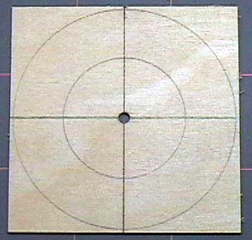 |
Drill a 1/8" hole in the center of the
former. |
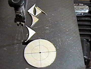 |
Trim off most of the excess using whatever
method you like. Leave enough material so the former can be sanded
to final shape. |
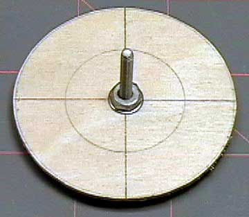 |
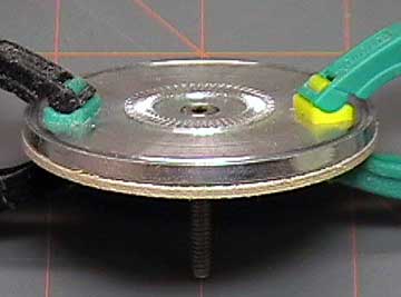
If you have a drill or a drill press you can
make final shaping really easy. Thread a 6-32 bolt through the former with a washer on each side.
Thread a hex nut on and tighten it securely.
Do not chuck this assembly into your
moto-tool unless you want to learn how cheap the bearings in these tools
really are. They will not last long with an unbalanced load such as
this. |
 |
Chuck the assembly in your drill or drill
press. Use a sanding block to take the former down to the line.
Notice that the bolt is threaded through so the lines are visible.
Do not continuously press the block against
the former. Instead, push the block up to the former until it just
touches. Then hold the block still until the high spots are
knocked off. Keep doing this until the former is to the line.
Turn off the drill and check the spinner
backplate against the former. Keep sanding until they match well.
You can also sand a slight taper into the
former by tilting the block so that the former matches the taper of the
fuselage. |
 |
I leave the ring slightly over-size so I
can finish sand it after it is glued on the fuselage. Here you can
see that the former is a hair larger than the spinner backplate. |
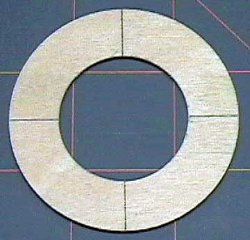 |
Cut out the inside of the nose ring when you are satisfied that the outside edge
is correct. |
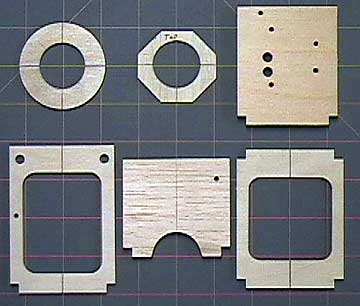 |
The complete set of formers from the nose rearward shown in order from
left to right, top to bottom.
The center former in the bottom row goes in
the center of the radio compartment. The cut-out at the bottom is
to pass wires from the
servo compartment to the
receiver/battery
compartment.
Note the former at the bottom left. This former is located at the
leading edge of the wing. The holes for the wing dowels are
already drilled to simplify
mounting the wing.
Note that the dowel holes are as far apart as possible. The
farther apart these holes are, the more stable the wing mount will be. |

