 |
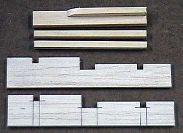
I use rails rather than plywood trays.
Trays require support rails anyway and are heavier. Trays are thin
and do not give servo screws much wood to thread in to.
These rails are cut from motor mount stock.
The center rail is 3/16" x 1/2" with a 3/16" square step glued on.
The fore and aft rails are both 3/16" square.
These rails are plenty strong and the mount
is very light. Rigidity is also important because if the servo
mounts can flex then play is introduced into the setup.
The rail supports are 1/8" balsa.
|
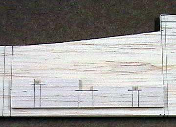 |
This is how the servo rail
supports will be glued to the inside of the fuselage. Notice that
the bottom of the support is 1/4" above the bottom of the fuselage.
This is to take into account the 1/4" longerons that will be glued to
the inside of each fuselage half. |
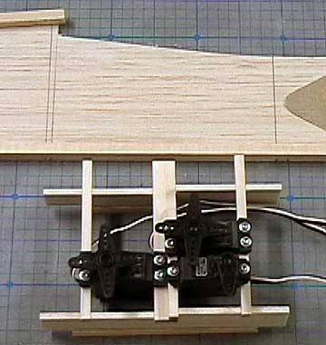 |
The servos are pre-mounted on the rails.
The rails are over-length so I will have to be careful when trimming
them to ensure the mounting holes line up.
To simplify this I line up one end of the
rails before mounting the servos. Now I just have to trim the
opposite end of each rail and they will remain in proper alignment.
In this image the front of the fuselage
is to the right. The elevator servo is mounted to the lower left.
The throttle servo is mounted to the lower right. |
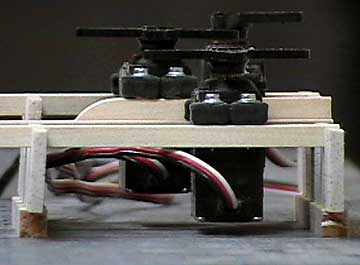 |
Here you can see the rail
supports sitting on scraps of 1/4" square balsa. The longerons
are taken into account when cutting the rail supports so that the
bottom of the servo is close to the bottom of the fuselage without
touching it.
The only part of the servo
that should touch any part of the structure are the grommets. If
any other portion of the servo contacts the structure then vibration
will be transmitted directly to the servo. |
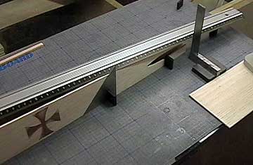 |
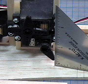
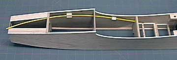
Locate the pushrod exits. Pull-pull cables will be
used but the method is the same for pushrods. I often see pushrods that bind where
they exit the fuselage and they do not align properly with the control horn. Normally
the builder cuts an ugly, gaping hole or bends the pushrod to relieve the binding. Temporarily assemble the fuselage sides
and formers. Pull the
tail end together. A straight edge is lined up over the hole
in the servo arm that the pushrod will be connected to. The
machinist's square represents the
fore-aft and side-to-side location of
the control horn.
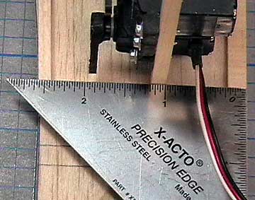
The triangle is located where the straightedge
intersects the outside of the fuselage. This is the fore-aft
location of the center of the pushrod exit.
|
 |
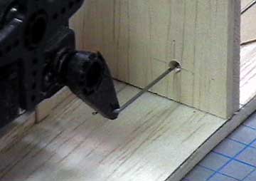
Drill or cut the pushrod exits. I have
a purpose-made tool
for cutting pushrod exits. |
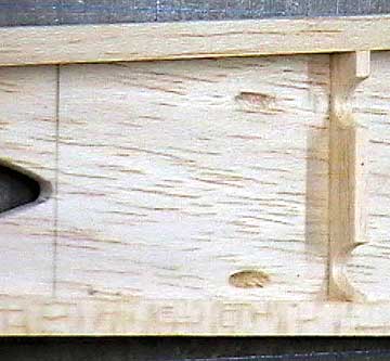 |
Here are the same holes viewed from the
inside of the fuselage. Note the vertical support has been
relieved. The cables may saw through it which would not cause a
problem structurally, but it would cause the cable to slacken. |
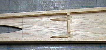 |
A 2" piece of inner
NyRod is glued in these
holes using thin
CA. The outside of the NyRod is trimmed and
sanded flush with the fuselage side. Again, this is for
pull-pull cables. For a normal pushrod, there would be one slot
and that is it. The inner NyRod pieces would not be used.
If using NyRods then the outer would be glued in the exit and
trimmed flush with the outside of the fuselage. It should run all
the way back to the radio compartment with cross-braces of about 1/8" x 1/2" bracing
the NyRod about every 3". |
 |
In this image the servo rails are not glued in place yet.
The lower servo is the
throttle servo. A hole must be drilled in the former immediately
in front of it to pass the throttle pushrod. The former is
represented by the two lines in the lower right-hand corner. A mistake that is often made is lining up
pushrod holes in formers with the servo when the arm is centered. That
only works if
the servo is far enough from the former to prevent binding when the
servo arm is rotated to the point where the arm is closest to the
former.
I line up holes in formers with the servo
arm rotated to where it is closest to the former as shown here.
Measure the distance of the hole from the fuselage side. This will
be the distance to the center of the pushrod hole in the former.
|
 |
The vertical location of the hole is
measured from the bottom of the fuselage. In this case a
Z-bend will be used
on the servo end of the pushrod. It will enter the arm from the
top. That means the hole in the former should be 2" from the bottom of the
fuselage. If a
clevis is used
then the hole will be centered on the servo arm. In this case the
measurement is 1-29/32". |
 |
The X-Y location of the hole is transferred
to the former and then drilled. You can see that it lines up very
well. It will not align perfectly when the servo is at center, but
it is close enough that it will not be a problem. The further from
center that the servo arm moves, the better the alignment. If
the hole lines up with the servo arm at center, then it binds everywhere
else - especially at extreme throws (full throttle and
idle).
Binding at idle in particular is a problem because that is where the most
precise throttle control is needed. |
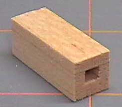 |
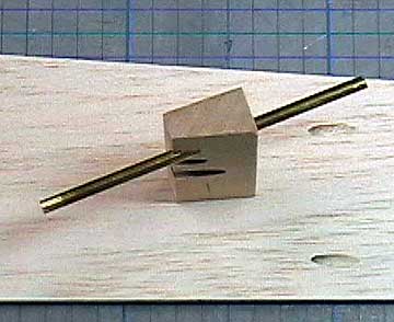
I use my
table saw to cut a 1/8" square groove in a
stick and then cap it with some scrap. The stick is then cut into pieces about
1/2" to 3/4" long and used to brace the housing for the throttle
pushrod. These grooves are easily cut with a hobby knife or a
piece of brass tube. You can use light, soft wood - strength is not
an issue here. |
 |
Slide as many of these pieces as necessary over the outer
housing to brace it. Allow the housing to find its own path as
much as possible. When it must curve for any reason, make the
curves large to prevent binding. |
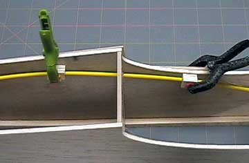 |
Apply glue to the blocks and clamp them in place.
The excess housing will be trimmed off about 1/8" from
the firewall because the throttle for the engine used in this aircraft
is behind the engine.
However, I normally allow about 1" of excess to help keep
the pushrod stiff. |

