 |
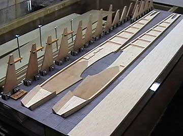
The completed fuselage sides on the board
ready for assembly. |
 |
Formers and other components that will be
used during the dry fitting. Always fit anything possible so that
potential problems can be corrected before parts are glued in place.
It is much easier to eliminate problems before parts are glued together
permanently. |
 |
Draw a centerline on your build board to assemble the
fuselage over. Pick one of the
formers in the
wing saddle
area to begin with. This is the former to the rear of the wing
saddle. It is erected perpendicular to the board and square to the
centerline.
|
 |
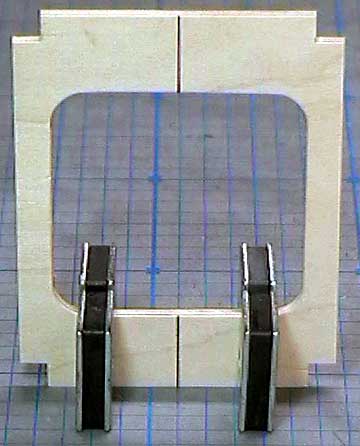
Most kits have a former at
the
leading edge and
trailing edge of the wing. For most of my
planes I build a former to
split the wing saddle area into two compartments.
This former simplifies keeping the
receiver and
battery pack in place. Of course
on larger models, the wing saddle area is so cavernous that this will not
work — the components need to be strapped down in some fashion.
This model is small enough that I can fill unused areas with
scraps of latex foam rubber.
Note that this former is made from two
cross-grain laminations of 1/8" balsa. |
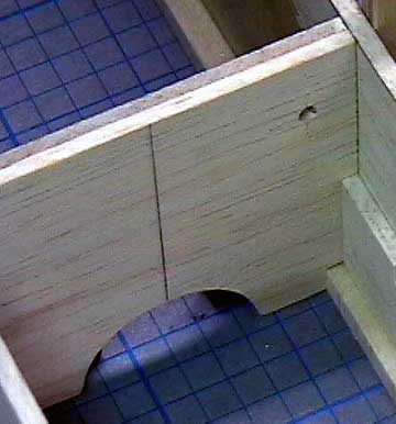 |
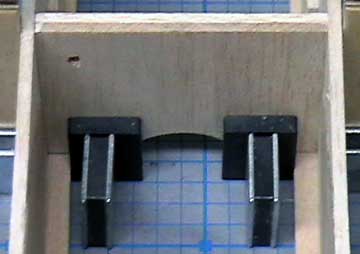
The rear face of the above former.
Notice that it butts against the
servo rail supports. Also note
the
throttle
pushrod guide hole and the cut-out at the bottom of the
former to pass servo wires to the receiver/battery compartment.
Be sure to smooth this edge carefully to
prevent it from sawing through the wires — especially if the former is
plywood. |
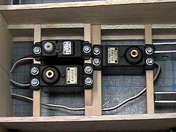 |
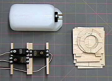
Details of the radio installation are
here.
The servos rails are ready to drop in. All seems well and
no further adjustments are necessary thanks to careful planning. |
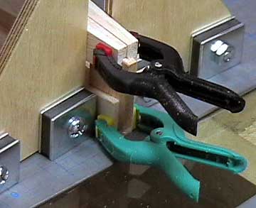 |
The tail is aligned over the centerline and
clamped. Even though the formers are centered and the tail post
aligns perfectly over the centerline, the fuselage is not straight aft
of the wing. Reasons this can occur:
- The fuselage sides are not identical
in length
- The sides vary in
hardness
- One side is ahead
of the other
The result of any of these conditions is a
fuselage that is not symmetrical.
Check that both sides align with each
other. A line drawn from a point on one fuselage side to the same
point on the other side should be perpendicular to the centerline.
Note the tapered tail-post piece.
It will be cut at the end of the fuselage construction to allow passage
of the
stabilizer. |
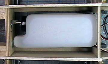 |
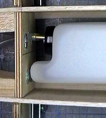
Check the
fuel tank installation by actually
installing it. In this case there is no tank hatch so the radio
compartment is the only way in or out without performing surgery.
Note that there is room all around the tank for foam rubber. The
selected tank will allow 12-15 minutes flights. |
 |
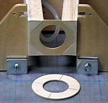
Careful measurements taken while building the
firewall ensure there will be no problems. You can see the tank is not strained in any way.
The fuel lines pass easily
through the
firewall
without radical bends or kinks.
The tank was blocked up to
the correct height for the dry-fitting. Latex
foam will support the tank when it is permanently installed.
The front
of the tank is pressed against the blind nuts. This is bad because
it is possible
for one of the
engine mount bolts to puncture the tank. The fix to
this is three-fold:
A piece of foam rubber will be
attached to the forward part of the tank to prevent the tank from
directly contacting the firewall.
The bolts will be cut to
so they do not extend past the blind nuts.
Do not dive the airplane into the
ground or fly it into walls or trees.
|
 |
The former directly behind the nose ring.
It is best to install this former with the engine installed.
However, this engine will be side-mounted and it requires a large
cut-out in the fuselage side.
I chose not to do this because the cut-out will be
so large that it is likely the fuselage would warp during construction
due to the sides not bending equally.
I have decided to place my bet on my building
accuracy and trust that the spinner will line up with the nose ring when
assembly is completed. This is a risk because the chance of having
a perfect match are about nil. That is why I left the ring slightly
over-size. I doubt it will be off by a significant amount. |

