 |
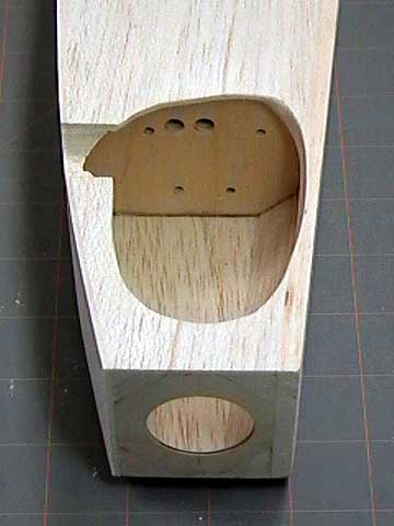
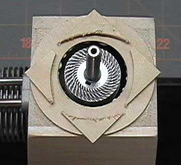
This was what the cut-out looked like
initially. The only part that I really do not like is the upper
edge of the cut-out (right side of photo) which would have looked better if it were a straight line. Other than that it is not horrible.
I can get the engine and mount in
and out easily and there is room to work around the engine without damaging
the wood.
Note the triangle stock in
the engine compartment. This is what allows the nose to have a
streamlined shape. |
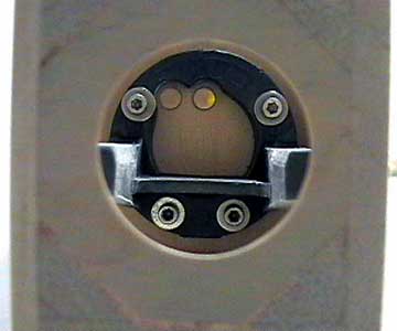 |
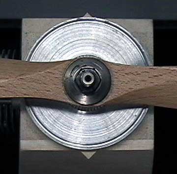
All the
engine mount bolts are secured
through this opening. They can be reached easily with a hex driver
(not an Allen key). If you look
carefully, you can see where the engine mount has been relieved to
prevent interference with the
fuel lines. The other option was to
drill the holes in a different location. However, the holes line
up with the
tank where they are and any other location would invite
kinking and fuel-feed problems. This was a problem that I solved when
I was building the firewall before it was glued into the
structure. I can not stress strongly enough the importance of
fitting anything and everything before gluing it in place to prevent
untold amounts of frustration. |
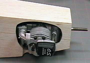 |
The next step is to glue on
the
spinner ring and shape the nose. The engine has to be mounted
before the ring can be glued on.
This is an O.S. .52 Four-Stroke. The rear mounted carburetor makes
hooking up a throttle linkage a challenge. There is not room
between the firewall and the
carburetor for a
clevis. A
Z-Bend will be difficult because the engine has to be removed by
pulling the back out first which means the wire will bend too much.
My buddy, Mike, suggested
that I use
music wire with an L-Bend that is sprung so it will engage
the throttle arm without using any type of connector. I did it and
it works great! |
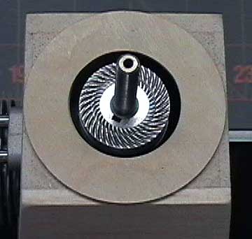 |
Apply glue to the ring and center it around
the prop shaft. Slide the spinner backplate on the shaft to align
the ring. |
 |
Use scraps of plywood to act as clamp
blocks. |
 |
Put the spinner backplate on with a
propeller and tighten it all down to clamp the ring while it dries. |
 |
When the ring has dried, remove the engine.
Plane, carve and sand the nose to shape. |
 |
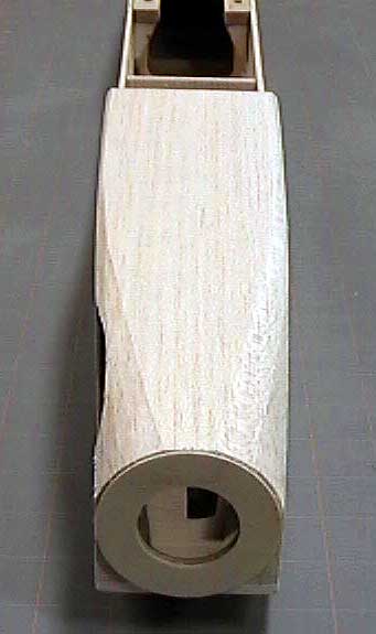
Continue sanding until the nose has a nice
flowing shape to it that fairs into the spinner at the front and into
the box fuselage further back. |
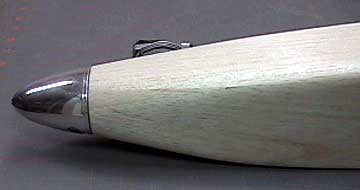 |
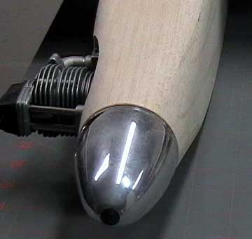
Another view of the nose. This is a
Fox Slim Jim spinner. I also have a Fox Conical spinner of the
same diameter. I think the conical spinner will look better, but
I will wait until the aircraft is finished to make that decision.
I do not see these spinners listed on the Fox
web site so they may be out of production. |

