Building
the
Thunder Tiger Raptor 30 V2 Helicopter — Step Six
Step Six
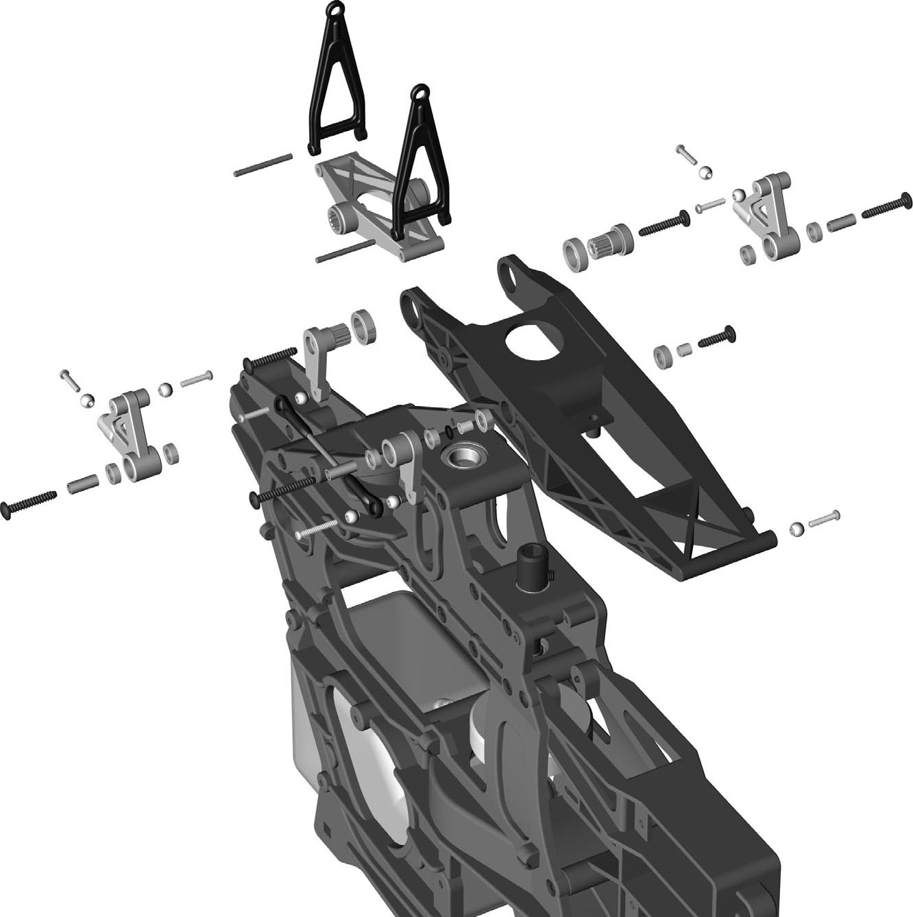
— Main Frame Assembly - Part 2
This step is on page 8 of the Instruction Manual.
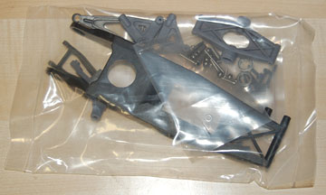
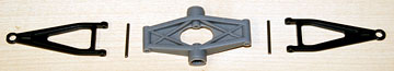
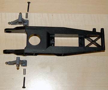
The parts bag for this assembly.
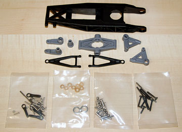
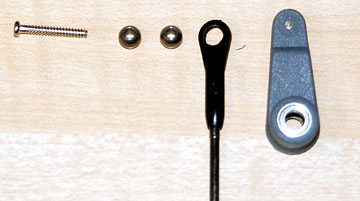
Parts for step two of the main frame assembly.
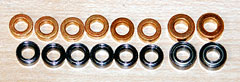
If you have the 29 bearing kit and don't have the bearing upgrade you
will use the bushings at the top of the photo. Otherwise you'll use
the bearings.
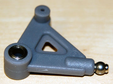
Parts for the elevator control arm assembly.
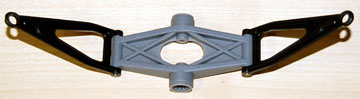
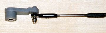
The assembled elevator control arm. The
pins slip through the elevator control arm links (black) and
are a press fit into the elevator control arm (gray).
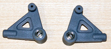
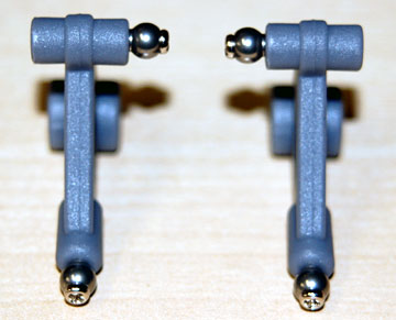
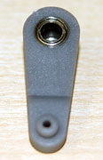
Press a bearing into each side of each aileron control
lever.
Use a self-tapping screw to mount a ball on the end
of each aileron control lever.
Again, note that the shoulder on the ball is opposite the
screw head.
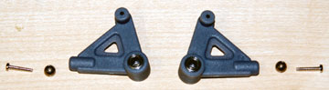
Mount a ball on one side of each aileron control lever.
The two levers should be mirror images.
Press a bearing into each side of the elevator control
lever.
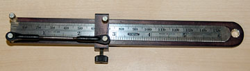
This is a handy tool made by Ace RC I believe. They
call it a linkage duplicator but it works just fine for making a single
linkage of a specific length.
Use the M2 x 14 self-tapping screw to mount two balls to
the elevator control lever.
The 66 mm linkage you make in this step connects to the
inside ball.
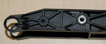
Press a bearing into each side of the collective pitch
control arm.
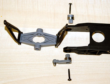
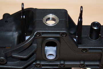
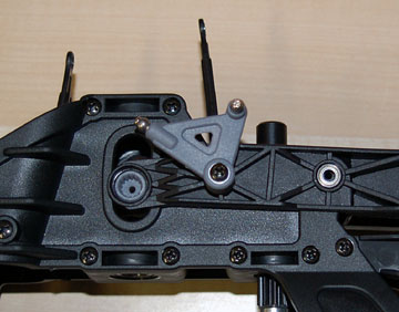
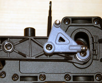
This is how the elevator control arm assembly is attached
to the collective pitch control arm.
Note that the elevator
control arm assembly must be inside the frame before it is attached to the
collective pitch control arm.
In this image I have bolted the aileron
control levers on the wrong side.
The balls on the ends go toward the rear as shown, but the balls on the
side are inside, not outside.
I could have removed the ball and moved it to the inside, but it was
simpler to just swap the arms.
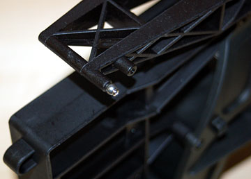
Place the elevator control arm assembly inside the frame.
The easiest way to do this is to tilt it about 45° and insert it from the
rear. When the shanks on the elevator control arm line up with the
frame cutouts, rotate the arm into position.
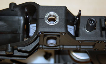
Another view of the elevator control lever inside the frame.
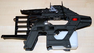
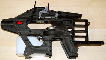
Place the collective pitch control arm on the frame.
The aileron control arms are still mounted on the wrong sides.
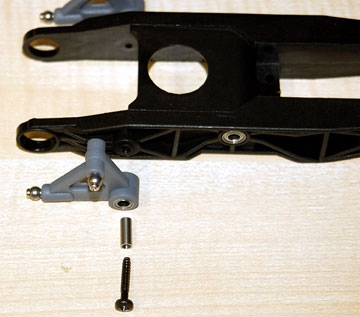
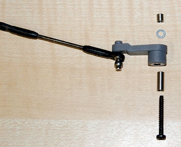
Parts to mount the elevator control lever to the collective
pitch control arm.
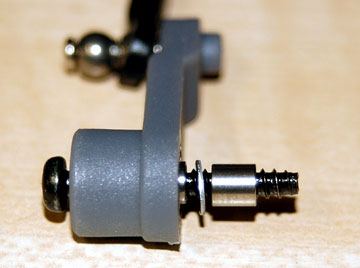
Place the long collar inside the elevator control lever,
insert the M3 x 18 self-tapping screw, slide on a washer and then slide on
the short collar.
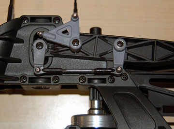
Mount the elevator control lever to the collective pitch
control arm.
Mount the elevator arm parallel lever to the
elevator control arm. It should point straight down when the
elevator control arm is horizontal.
Both levers go on the right side of the heli as viewed from the
cockpit.
Attach the linkage to the two levers.
Mount the elevator control arm shaft to the left
side of the elevator control arm.
Mount a ball on the forward most post on the front left
side of the collective pitch control arm.