Landing Gear
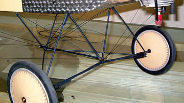 The landing gear is shock absorbing, scale in appearance and
appears very durable.
Although there are many pieces, it looks more complex than it actually is. I
hope you enjoy soldering though. There are 20+ solder joints in the gear and
many of them are wire-wrapped. I used regular rosin-core solder throughout. The landing gear is shock absorbing, scale in appearance and
appears very durable.
Although there are many pieces, it looks more complex than it actually is. I
hope you enjoy soldering though. There are 20+ solder joints in the gear and
many of them are wire-wrapped. I used regular rosin-core solder throughout.
Don't cook the solder joints or you will change the temper of the music wire
and significantly weaken the gear.
I suggest that you use a small torch (carefully) or a heavy-duty
soldering iron. The type iron used for electronics work probably can get
the job done, but takes a very long time
to heat the large joints to the point that the solder will flow properly.
All the pre-bent pieces fit well except the triangular piece in the first
step. It didn't match the piece it is wrapped and soldered to so I pulled
out my
wire bender. I went back and forth bending and fitting until I was
happy with the fit.
One thing that would be nice is for the manufacturer to specify how long to
cut each piece of wrapping wire. I had no idea so I took a wild guess and
then added some to that. Because of that several pieces were cut way over-length
leaving excess that was too short for other pieces. I ended up not having
enough copper wire for the whole job. Enough is supplied if you more
accurately guess correct lengths than I did.
Running out of wire didn't cause any problems for me because I keep the stuff
on hand. You can get fine copper or brass wire at most hardware stores.
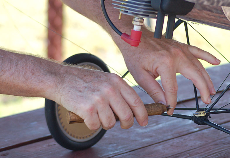
We put a lot of load on the landing gear when we were rigging the model.
We pushed down hard on both wing tips to bow the wings so we could attach the
flying wires to the landing gear. The gear can take a lot of force and
spring back to its original position. One solder joint broke where music
wire goes into a brass tube. I pulled out a small torch and silver
soldered the joint using a very small bit of acid.
The Klass Kote paint did not burn off. It did turn a little darker and
shinier. I like it better. I think I just invented baked epoxy
enamel paint. OK, I didn't, but I'm thinking of torching the whole gear to
see if it makes the paint harder. If I'm wrong and the paint burns off
then I get out the steel wool and repaint.
 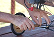 Mike
made a nice tool to help assemble the model at the field. It is very
high-tech consisting of a cut-off 1/16" drill bit CA'd into a dowel. It
works great! Mike
made a nice tool to help assemble the model at the field. It is very
high-tech consisting of a cut-off 1/16" drill bit CA'd into a dowel. It
works great!
I wrote a
very detailed article about painting the wheels so you can read about the
wheels there. When I began on this model there was a discussion about
drilling big holes in the wheels to save weight. I won't mention names,
but it wasn't my idea. I said, 'Let me paint the wheels and then see how
much you still want to save that weight.' The wheels made it to the end
having only an axle hole.
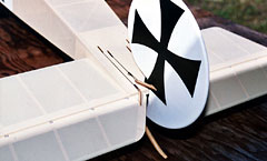
I'm very happy with how the wheels came out. Several people have told me
that they aren't actually "scale" wheels. Wheels used in WWI had spokes
that overlap just like bicycles and motorcycles have today. They were also
dished meaning that the hub was off-center to the outside when viewing the
aircraft from the front or back. Ok, so the point is that these wheels are
the same scale as the rest of the model. Better than close enough for fun.
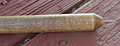
 The tail skid is laminated from 3 pieces of spruce which are then sawed and
sanded to final shape. It's a focal point of the model and worth taking
your time with. The tail skid is laminated from 3 pieces of spruce which are then sawed and
sanded to final shape. It's a focal point of the model and worth taking
your time with.
I decided to make the skid from beech stock. After final shaping, I
fiberglassed it with a piece of 0.5 ounce cloth on each side. I sanded the
fiberglass after the resin cured and then sprayed
two wet coats of satin clear Klass Kote.
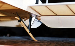
The skid mounting requires some wire bending, but isn't too difficult.
If you don't like it and can't fix it, cut the wire using an emery wheel in a
Dremel and try it again with a new piece of music wire. Fit and
adjust until you're happy. This is the only portion of the kit where it
isn't pretty much spoon fed.
Like the main gear, the tail skid is shock absorbing through the use of more
elastic cord. This model will be flown off grass so we didn't do anything
special to save the bottom of the skid. As it wears we plan to apply thin
CA every so often until a hard, long-lasting surface is achieved.
|


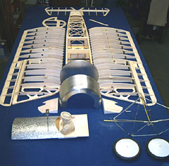 Wing panel construction consists of balsa and lite-ply ribs with 2 carbon
fiber tube spars and a carbon fiber tube leading edge. The trailing edge is
laminated from one wide and one narrow 1/8” thick balsa strip.
Wing panel construction consists of balsa and lite-ply ribs with 2 carbon
fiber tube spars and a carbon fiber tube leading edge. The trailing edge is
laminated from one wide and one narrow 1/8” thick balsa strip.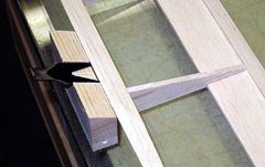 The ailerons are simple and quick building. The leading edge of the ailerons
taper at the tip when viewed from the front. I sanded one aileron and then matched the other to it.
Then I sanded the aileron bays to match the ailerons.
The ailerons are simple and quick building. The leading edge of the ailerons
taper at the tip when viewed from the front. I sanded one aileron and then matched the other to it.
Then I sanded the aileron bays to match the ailerons.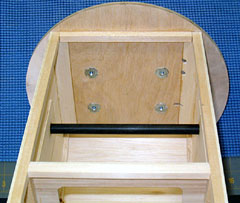 The fuselage is
a cavern built primarily from lite ply and spruce
(which looked and performed more like basswood than spruce). The firewall is
laminated from two pieces of lite-ply and one of birch.
The fuselage is
a cavern built primarily from lite ply and spruce
(which looked and performed more like basswood than spruce). The firewall is
laminated from two pieces of lite-ply and one of birch.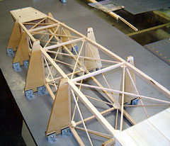 The instructions
indicate that the cross-bracing should be temporarily left out of one bay to simplify the pull-pull cable
installation. I don't install cables until the model is covered and
painted so I ignored this instruction.
The instructions
indicate that the cross-bracing should be temporarily left out of one bay to simplify the pull-pull cable
installation. I don't install cables until the model is covered and
painted so I ignored this instruction.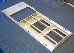 The upper deck is made from a lite-ply base having several lite-ply formers
that lock into notches in the base. I suggest that you face the instrument
panel with a thin veneer to improve its appearance. As designed there are
pieces that notch into the panel that will be visible and unattractive.
The upper deck is made from a lite-ply base having several lite-ply formers
that lock into notches in the base. I suggest that you face the instrument
panel with a thin veneer to improve its appearance. As designed there are
pieces that notch into the panel that will be visible and unattractive.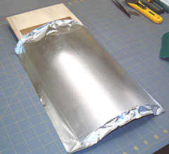 I
I
 There is nothing difficult about building the tail although I don’t care for
the design. Every piece of the stabilizer and elevators is laminated with the
exception of the carbon fiber tube outlines. The lamination is mostly
unnecessary.
There is nothing difficult about building the tail although I don’t care for
the design. Every piece of the stabilizer and elevators is laminated with the
exception of the carbon fiber tube outlines. The lamination is mostly
unnecessary.