Building
the
Thunder Tiger Raptor 30 V2 Helicopter — Step
Thirteen
Step Thirteen
— Tail Unit Assembly
This step is on page 12 of the Instruction Manual.
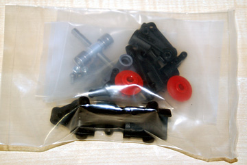
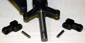
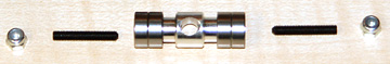
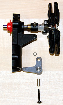
The parts bag for this assembly.
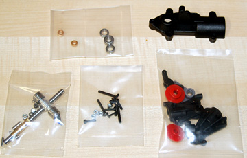
Parts for the tail unit assembly.
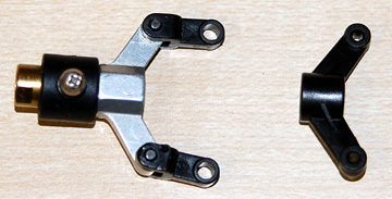
I broke several tail pitch control forks on my
original
Raptor when I was first learning to hover and dragged the tail across
the ground. I finally bought the metal fork which is much stronger
and survived the crash.
I will use the metal fork because I have
it.
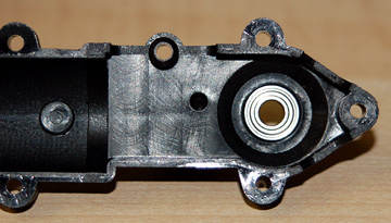
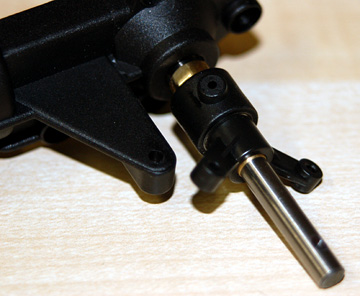
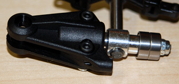
Insert the bearing into the right tail unit housing.
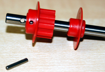
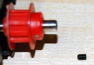
Slide the tail pulley and tail pulley flange
onto the tail rotor shaft. The flange goes toward the right
housing.
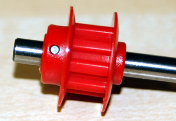
My thanks to Emiel Koning for pointing out that I
put the tail pulley flange on backward. If you look at the next
image you can see there is a slight taper on one side of the flange.
The taper should be against the gear with the flat side out.
I have to disassemble this unit to correct it so I'll take new photos at
that time.
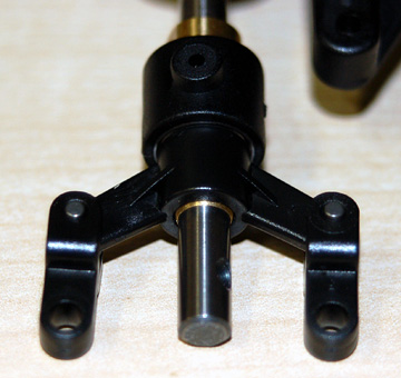
Press the pulley and flange together and line the pulley up
with the hole in the shaft. Insert the pin.
Again,
the flange is backward and should not be installed as shown.
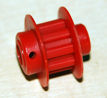
This is how the tail pulley and tail pulley flange should
be assembled.
If you look at the flange you will notice that
there is a long shank and a short shank.
The short shank goes into the tail pulley.
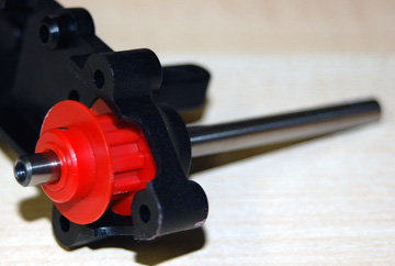
Slide this assembly into the bearing in the right housing.
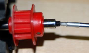
This set screw prevents the pin from coming out.
Apply Loctite in the tail rotor shaft, insert the set screw
and tighten it against the pin.
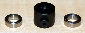
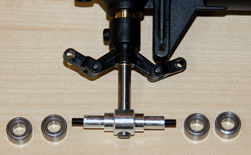
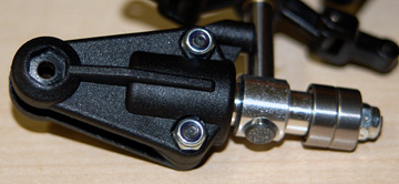
Insert two bearings into the tail pitch control
slider.
Slide the tail pitch control slider bushing onto the
tail rotor shaft. Slide the tail pitch control slider onto the
bearing.
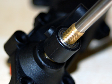
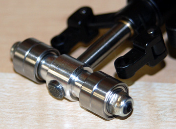
Thread the tail pitch control fork onto the tail pitch
control slider bushing. The bushing has two flats so it can be
gripped with an open end wrench.
If you have the metal fork be
sure to use Loctite when you thread it onto the bushing.
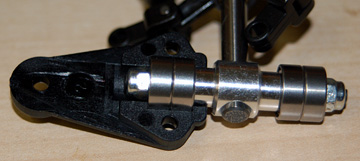
Tail pitch control links and pins.
Place the tail pitch control links over the fork and insert
the pins. The pins are a press fit. If you can not insert them
by hand, use the plastic handle of a screwdriver or hardwood block to
press them in place. Don't beat on them. They aren't that
difficult to push into place.
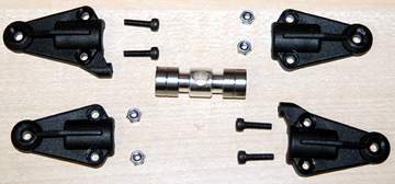
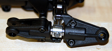
Tail rotor hub, tail pitch housings,
bearings and hardware.
Tail rotor hub, set screws and lock nuts.
Place the tail rotor hub onto the tail rotor shaft.
The shaft has dimples to receive the set screws. It is very
important that the set screws engage them.
The best way to do it
is to insert only one set screw, tighten it until it just contacts the
shaft. Back it off a half turn and then try to rotate the hub.
If you can rotate the hub only a couple degrees in each direction before it
hits stops then the set screw is in the dimple and can be tightened.
Insert the second set screw and tighten them both securely. Be
sure to use Loctite on both set screws.
Replace the bearings, add the lock nuts and tighten them
securely.
Place one tail pitch housing over the bearings.
Place the mating tail pitch housing on the bearings.
Press the lock nuts into the recesses and bolt the housing
together.
Repeat for the second housing set.
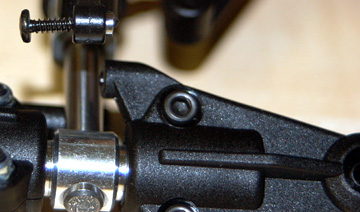
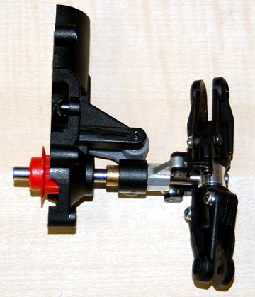
Insert a collar and self-tapping screw into each of the tail pitch control links.
Note that the link is in front of the leading edge of the
tail rotor blade. This is the correct orientation when viewed from
the right side of the helicopter.
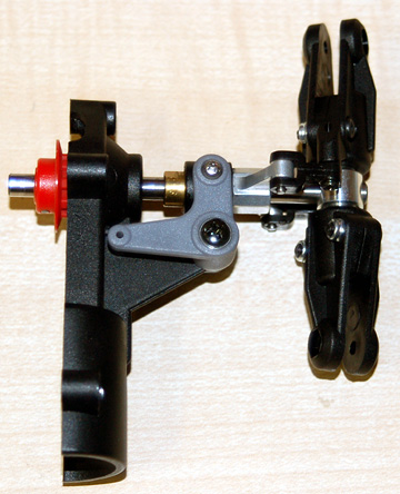
Turn the housing upside down to mount the tail pitch
control lever. Note the small washer.
Thread a
ball on the tail pitch control slider.
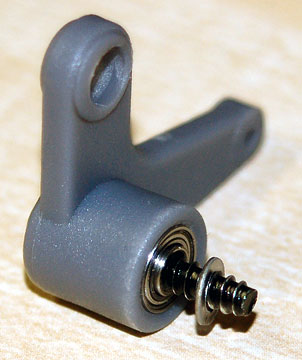
Insert a bearing into each side of the tail pitch control lever.
Insert the collar into the tail pitch control lever.
Note which side the screw is inserted from.
The
washer goes between the bearing in the tail pitch control lever and the
tail unit housing.
Place the larger hole in the lever over the ball in the
tail pitch control slider.