![]()
|
|
|
|
|
|
|
|
|
|
|
|
|
|
|
|
|
IntroductionAntonio has sent me a number of e-mails in regard to his Submarine's designs. I've been watching as he has evolved this design. He's had his share of mishaps and setbacks and has stuck with it which is how a really good design comes about. People who give up never achieve success. With his contest submission, Antonio sent almost two hundred photos, more than a handful of videos and separate articles for each portion of the model. A lot of effort has gone into the design and documentation of this model. Text, photos and linked photos that follow are Copyright Antonio Amado
|
|
|
About the Submarine MK IIModel airplanes started to fascinate me in my teens. Back then I designed and built a few free flight gliders and rubber powered models. Later I bought a glow powered kit and tried to fly it without any help which resulted in a series of crashes and repairs until the model was fully destroyed. The hobby was put on hold for many years after that. A year ago I purchased an OS .10 engine from the local shop and decided to design and build an RC model. I found the Airfield Models site when I was searching the internet for design advice. The model had 3 channels and came out ok for a first RC design. At the field someone asked me if it was a submarine because the fuselage without the wings resembled a submarine and the name stuck. Submarine flew well according to club members review but I lost it in thick fog on the third flight. Not yet found... A new plane had to be made and so Submarine MKII was born. The field is at high altitude and usually windy so I had to keep that in mind in the new design. I opted to use flaps because I read a little about them on the NextCraft website. Goals
|
|
|
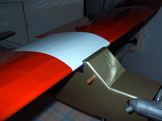
WingI kept in mind the importance of the wings and took into account effects that are greatly guess work. Because I started with the wings and was a bit eager to get on the job the planning work was a bit rushy. I used the Submarine 1 as inspiration and the shapes are very similar, just with a lower aspect ratio. I wanted more surface with the same span. The dihedral is on the ends, a reminiscence from my early days of model building. Also making the central part flat helps the fitting on the wing saddle. I made a nice plug with two dowels to fit on a socket on the fuselage. This will help getting the wings in place and keeping them there. The airfoil is a modified Clark Y. It is slightly thinner and the leading edge is slightly modified as well. This happened because I bought the leading edge strip already shaped and had to follow that shape. It would be harder for me to shape it with the tools I have. If I had a router I would make a router bit to shape it. Routers that cope with this job are really cheap, but making a good set up would be time consuming and my space is limited. Weighing the pros and cons I decided to buy ready shaped leading edges. I think the sacrifice in performance will be minimum, if any. I am going to try to find some free foil analysis software and check it out. I think that a lower thickness of the foil will help when its gusty... I think. For slowing down the flight the flaps come in. I am afraid I made the ailerons too small. The setting is to maximum physical throws allowed which isn't a great deal out of ordinary, if anything at all. The flaps are controlled with a proportional channel and go from 0 to 40 degrees. The ailerons have individual servos and are connected in a y harness to a small gyro which is connected to the radio. I only have six channels and I used the gear channel to control the gyro gain. There are three steps on gyro gain — off, 50% and 100% . The idea of a gyro on the roll axis was to make landing approaches easier. I don't know yet if it will help. I took some time with the flaps and the pictures show how I made them. The flap and aileron linkages are documented in pictures. I made the control horns for the flaps out of a scrap plate from the hard disk bay of a computer. The aileron servos are placed to work on the same axis plane as the ailerons.
|
|
|
FuselageThe firewall is made out of a lamination of 3 and 1 mm hard ply. The front of the fuselage is reinforced with 1 mm ply all the way to the wing saddle. The skins are 1.5 mm balsa and the rear formers are 2 mm balsa. The tail is fixed to fuselage by 2 pieces of 2 mm threaded rod. They go through brass tubes that are glued inside the fuselage and held on the other side by self locking nuts. The servo bay is 5 mm balsa reinforced by 3 mm ply where the servo screws attach. LinkagesI wanted to keep weight at minimum so I decided for 0.8 mm music wire pushrods. This option was tested on the first Submarine and no signs of flutter were noticed. For the engine I used 0.8 mm carbon fiber rod with bits of brass tube epoxied to the ends. I soldered the same type brass tubes on the music wire. I used EZ connections on both ends of the throttle rod. On the engine end the EZ connection has a washer and is held in place by two nuts. I put a drop of non permanent loctite on them. No slop, no signs of going anywhere. The forces are minimal.
|
|
|
Landing GearFor the landing gear my goal was to make it strong and replaceable. On the main gear I used 3 mm music wire for the front part and 2 mm to reinforce it and keep it in place. It is mounted close to the firewall where structural strength is the highest. The right location was found after some weight distribution considerations. The gear is screwed into two hardwood strips that run along the front of the fuselage at the bottom and are interlocked with the firewall. There is balsa on the sides of these strips to fill the width. Fiberglass was laid at the bottom and finished with a layer of 1 mm plywood. There are pictures of this work that are self explanatory. I think that the location close to the firewall will help on steep landings. The gear will tend to hit the ground before the propeller. The rear wheel is simple. I bought it, modified the mount a bit and screwed it on using two screws.
|
|
|
Tail groupAfter strenuous V-Tail brainstorming I postponed the idea to another project. Not because it's difficult to design — there is enough info around about them and I wasn't too concerned about how this configuration would affect the flight. It's tools.. I haven't got enough of them. The mount would be harder for me to do than a conventional tail. I wanted the tail to be easily repaired or replaced and for that I found the V-Tail mount much harder to do with my tool limitations. Right angles are much easier. As a beginner flyer I am very aware of the possibly of crashes and hard landings. I saw at the field one trainer fuse being broken by the tail on landing. Just before the flight the plane owner was telling me that he had a new stabilizer made out of solid balsa to replace the built up original one that broke. The unfortunate fellow had now a too rigid and heavy tail that was too good to break and instead the fuselage gave in. I prefer the tail to break. He lives in an apartment and has kids so it is hard for him to find room and peace for repairments. Maybe this is one reason why ARTFs are so popular. Not just laziness, but that is another story. Going back to the tail and tail mount... I came up with a system that I haven't seen anywhere but has probably been around since the beginning of this hobby. I put two bits of 2 mm threaded rod on the fin and reinforced the fuse tail end with two horizontal pieces of 1mm ply. The rods run through brass sleeves and I designed it to prevent any parts to get squashed on tightening. I made a drawing and took some pictures showing this. The horizontal stabilizer is held in place between the fin and the fuse. It seems reasonably strong and stable yet fragile enough to break without damaging the fuse. To take this assembly out is a 2 minute job. Just free the pushrods from the servos and take two small nuts out... off it comes. I am happy with this design. Much harder to achieve with a V tail.
|
|
|
Design and Build — Crash and RepairI finished the plane and went test flying it. It took off very well and tracked straight for a model this size. The flight was very stable and control authority was great. On the third flight catastrophe struck. At full throttle I pulled the elevator full up and the stabilizer broke. The plane came down uncontrollable from fifty feet up and hit the ground very hard. After a first look at it and identifying what went wrong I decided that it wasn't worth repairing. The next day I took a better look, reevaluated the wreck and decided to repair. The front section survived the crash. It has the firewall and landing gear mounts. It was scraped and cleaned to the state you see in the photo and that was the only usable part of the fuselage from which to start to rebuilding. The color scheme is white and red before the crash. The repaired fuselage is gold (I am very limited by the colors of the local shop). All the flight videos I sent were shot after the plane was rebuilt from the crash parts. The plane you see on the videos is the final version. I rebuilt the fuselage and the tail and on the wings I redesigned the flaps, replaced sheared servos and re-covered it all.
|
|
|
JudgingOf all the entries I received for this contest, Antonio put the most effort into his. His photo documentation is outstanding and doesn't leave me wondering how his model is built. Additionally, he has been developing this model for quite some time and has made numerous improvements to the model through the course of its development. What I like most about this model isn't the model at all. It's Antonio's attitude about model aircraft in general and his willingness to avoid conventional wisdom and try his own ideas. Assuming he sticks with it I think it won't be too long before he starts producing designs that mix and match various techniques he learns into one-of-a-kind model aircraft. Antonio shows that he cares about the quality of his craftsmanship even if it will never be seen again after it's covered. So why did this model come in 3rd? The one thing that really stands out to me when looking at the model is that it is just too complicated for what it is. Again, I think that's good in its own way because Antonio will learn a lot by experimenting. But the contest isn't judging what you learn in the process. It's judging the final product and how it got there. This model could have been substantially simpler while ending up with the same model aerodynamically. For example, the flap design makes me think that Antonio was thinking too much. When the flaps are up there is no gap, but there's still all that hardware hanging out in the breeze under the wing. I doubt that the improvement over a single bevel flap design is even noticeable and the added complication of the design as is just doesn't seem worth it. There's a consistency issue as well. I wonder why would one go to all the effort of marginally improving the efficiency of the flaps but accept the drag penalty of dowels and rubber bands holding the wing on? Antonio laminated some pieces in place using fiberglass cloth between the pieces of wood being laminated. In the areas he did that it really wasn't necessary. That kind of beefing up isn't needed for normal loads placed on a model in flight and handling and it hasn't proven to be effective in preventing damage in a crash. While the design of the model is too complex, it is well built and the moments and areas appear to be of proper proportion. I really like that Antonio is thinking and trying different things. I hope he continues in this hobby and continues to develop his own designs. I especially hope he continues to document them because it will be very interesting to see the progression of his designs over time. Congratulations on developing your model and bucking the norm, Antonio. I like the way you think.
|
|
|
|
|
|
Back to 2006-2007
Design and Build Contest
|
|
|
Copyright © 2007 Paul K. Johnson
|
|