Assembling the Throttle Hardware
 The
throttle is as close to a no-load
situation as you are going to get. A small
servo will work fine but you
want the entire setup to be as mechanically positive as possible. When you are landing
your aircraft it is important to have fine control over the throttle near
idle.
If there is any play or excessive drag in the setup then the engine will not respond properly to
throttle commands. The
throttle is as close to a no-load
situation as you are going to get. A small
servo will work fine but you
want the entire setup to be as mechanically positive as possible. When you are landing
your aircraft it is important to have fine control over the throttle near
idle.
If there is any play or excessive drag in the setup then the engine will not respond properly to
throttle commands.
Traditionally the throttle
pushrod has been a flexible cable. I have never been satisfied with
cables because they flex when I don't want them to and don't flex when I do want
them to. The other problem with cable is that it is unnecessarily heavy.
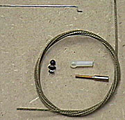
If you choose to use a throttle cable it is most often hooked up with an
EZ connector at the servo end and a solder coupler with a
clevis or
ball link at the throttle end. The problem with EZ connectors is that
they are inherently sloppy. The plastic fitting that holds it in place will
not stay tight for very long.
The way I set up cable is to use a
solder clevis at the servo and a
solder coupler with a ball link at the throttle end. That eliminates
the play associated with EZ connectors and it is a much more reliable. EZ
connectors have been known to become EZ Disconnectors at the worst possible
moment. The pilot is then in a situation where he has no throttle control.
Use sharp side-cutters or an emery wheel in a
moto-tool
to cut cable. If you are
careful you can cut it without fraying it. The wire
strands can usually be put back where they belong without much difficulty if
individual wires in the cable unwind.
One way to avoid fraying is to solder the cable before cutting it. If you
don't solder the cable ends before cutting them then you should solder
afterward.
Deburr the ends
of the cable using a grinder or an emery wheel in a moto-tool. The cable
will be less likely to cut you when working in the engine compartment or radio
compartment, will not fray and will slide more easily into place.
My preferred throttle linkage is simply a piece of 1/32" (0.032")
music wire with a
Z-bend at both ends if the engine uses a plastic (nylon) throttle arm. With a little practice you can put a Z-bend
exactly where you want it. The only drawback to this is that you can't
disconnect the linkage from then engine before you remove it. That is not
much of a problem though. After you remove the engine mounting
bolts you simply turn the engine to release the linkage. If you prefer
you can use a solder coupler and clevis on one end of the pushrod.
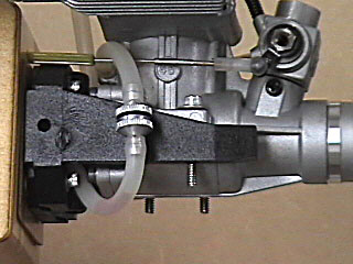 |
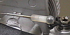
This is the business end of the throttle
linkage. An inner
NyRod houses a small diameter music wire pushrod. A solder
coupler is soldered to the end of the music wire. A ball is bolted
to the throttle arm and the nylon ball link is threaded onto the
threaded coupler. Dubro makes 1/32" solder couplers having a 2-56
thread that are perfect for this.
The fuel line could probably be situated
better so that it does not come into contact with the linkage but in
this case it is not causing any problems.
Also note the plywood
thrust wedge behind the engine mount. This wedge is probably
about 1/2°.
If you pay attention to small details like this you can make almost any
aircraft fly well assuming it was built straight to begin with. |
 |
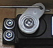
I like to use a Z-bend on the throttle end
as I do on the servo end. In this case the throttle arm is metal.
I decided against a Z-bend to avoid metal-to-metal contact which can
cause radio interference as well as premature wearing of the parts. |
 |
A simple Z-bend on the servo end saves money
and simplifies the installation. You only need one end of the
linkage to be adjustable if that. Normally you want to be able to
make adjustments outside the aircraft so there is no reason to have an
adjustable linkage here. |
The advantage of 1/32" music wire is that is
easier to work with, lighter and stiffer, yet is still flexible and much less expensive
than a cable setup. Overall it has every advantage of cable and
none of the disadvantages. I have found throttle control on my aircraft to be much more
positive once I switched away from cable. It is especially important to
have good control authority around idle where you want the engine to respond to
even the smallest commands.
The pushrod must be enclosed in some type
of housing inside the aircraft. The housing guides the pushrod and
prevents radio components and the fuel tank from interfering with its movement.
I groove small balsa blocks to fit the outer housing and space the housing about
1/8" away from the fuselage side.
|

