Building
the
Thunder Tiger Raptor 30 V2 Helicopter — Step Three
Step Three
— Main Frame Assembly - Part One
This step is on page 6 of the Instruction Manual.
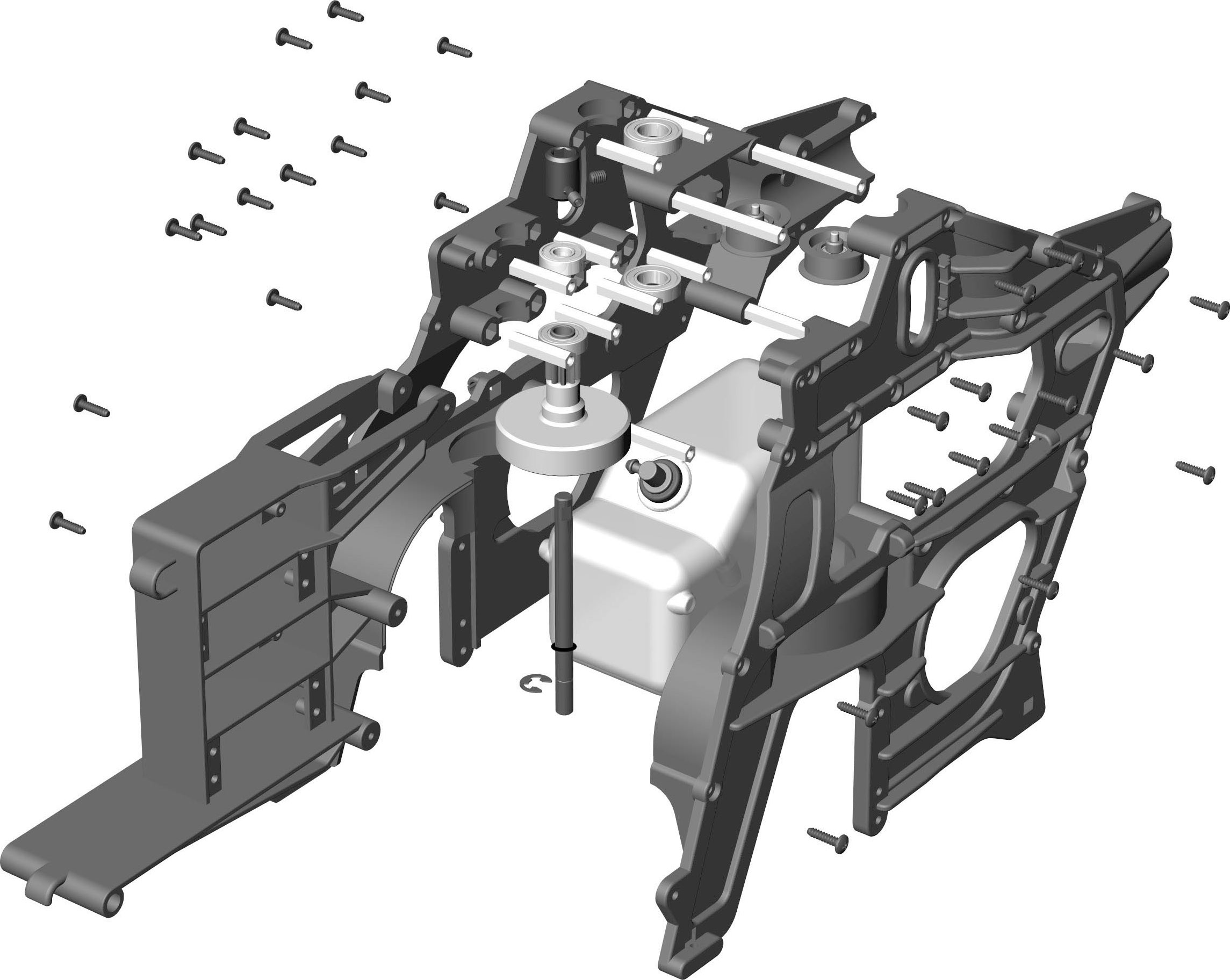
By the end of this step the frames will be joined having
everything in between that must be added beforehand.
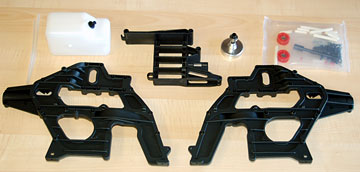
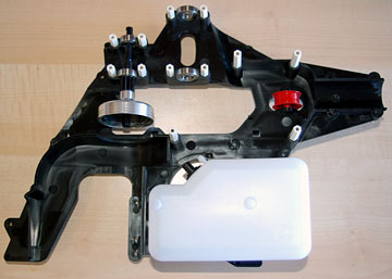
The parts needed for this step. Put the fuel line
aside for now. We won't add it until the helicopter is built.
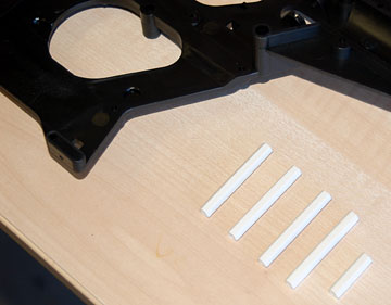
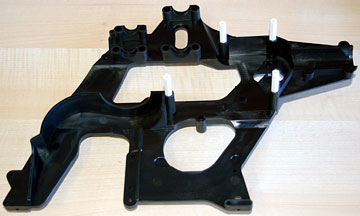
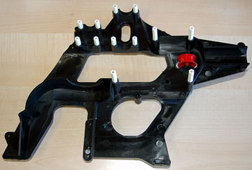
You'll notice that there are two lengths of frame posts.
There are four long posts and eight short posts.
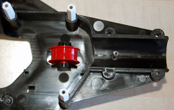
These are the locations of the long posts.
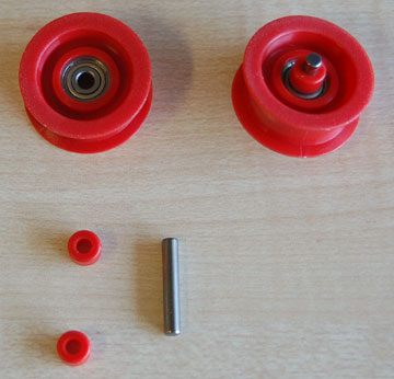
Assemble two guide pulleys. These pulleys push
the tail rotor drive belt together so that it doesn't rub on the frame or
tail boom.
Place a collar on the pin, slide the pin through the
pulley and then push a collar on the other end of the pin.
The pulleys are located just in front of the tail boom.
Stops are molded in that will prevent the pin from coming out.
One pulley goes in each half of the frame.
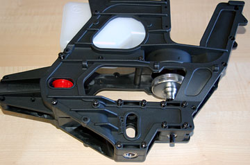
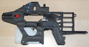
The pulley and all of the posts in place. You can
screw the frame to the posts now or wait until the second frame half is in
place.
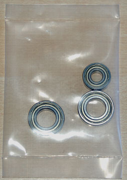
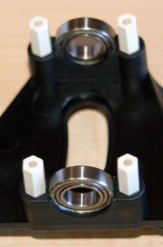
These three bearings must be in place before the frames are
joined.
The two larger bearings are for the main shaft. The
smaller bearing is for the starter shaft that engages the clutch.
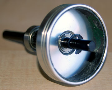
The main shaft bearings.
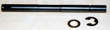
The starter shaft.
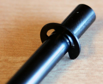
Place an E-clip in the groove cut into the starter shaft.
Slide the washer up to the E-clip.
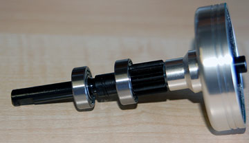
Slide the starter shaft into the clutch bell with the
E-clip and washer inside the bell.
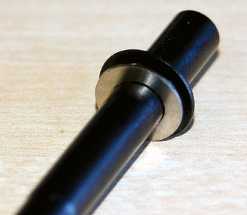
One bearing is already on the drive gear. Slide the
second bearing on.
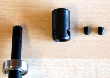
Clean the end of the starter shaft with alcohol. Also
clean the set screws and starter coupling.
The starter coupling allows a 6 mm hex shaft to be used in your electric
starter to start the engine.
The starter shaft has two flats on the end for the set screws to
engage.
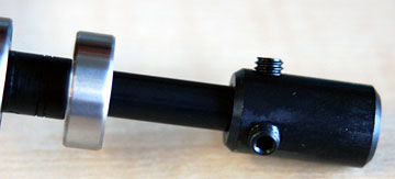
Put Loctite on each of the two set screws and insert the screws into the starter
coupling just a couple of turns.
Slide the starter coupling onto the starter shaft and
tighten the set screws lightly against the flats.
After the
frames are bolted together, loosen the set screws slightly. Push the
starter shaft up against the inside of the bell. Push the starter
coupling down until it touches the bearing. Securely tighten the set
screws.
Oil the shaft using a light oil.
Place the clutch bell/starter shaft assembly in the frame.
Add the fuel tank. The fuel tank has two molded protrusions
that engage the frame. You'll see where they are when you get there.
Align the second half of the frame and slide it onto the
posts. Screw both frames to the posts.
Be gentle when
tightening these screws. They will not come loose on their own.
If you tighten them too much the plastic will strip.
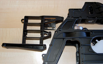
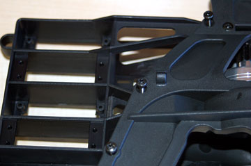
Insert the servo frame and screw it in place from
both sides.
These are the three screw locations that hold the servo
frame in place.