Building
the
Thunder Tiger Raptor 30 V2 Helicopter — Step Eleven
Step Eleven
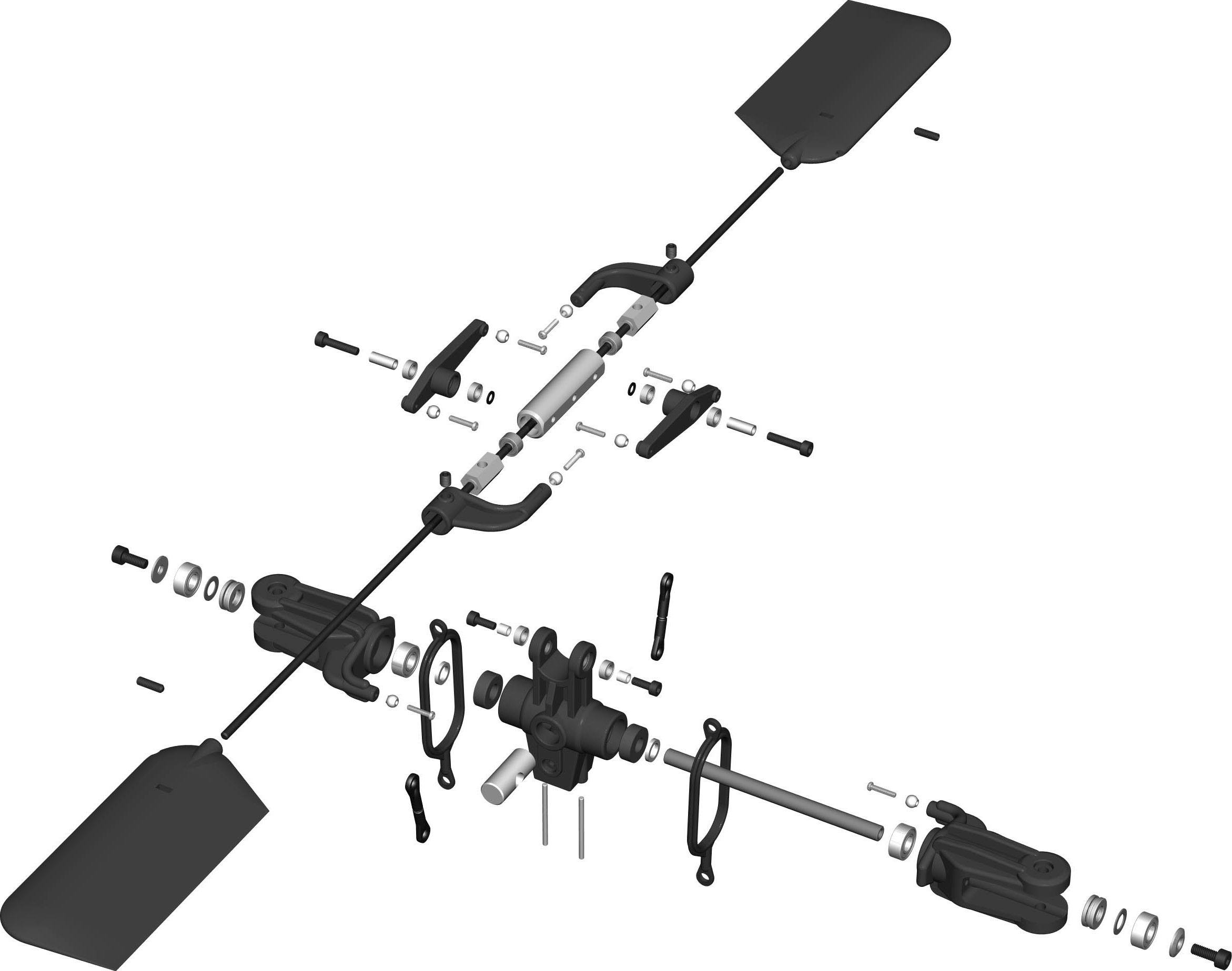
— Main Rotor Head Assembly
This step is on page 11 of the Instruction Manual.
This is probably the most complex step in building the
Raptor. It's not difficult but can be confusing in certain areas.
I've taken additional photos to help clarify what needs to be done.
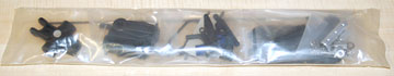
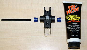
The parts bag for this assembly...
which breaks down into several more parts bags.
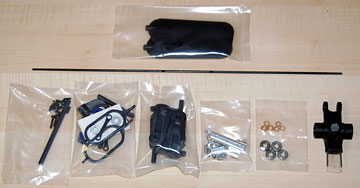
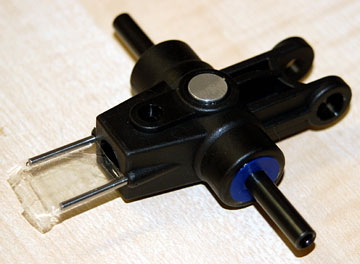
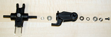
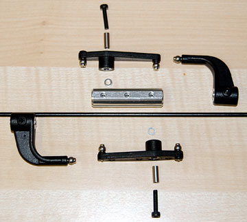
Parts for the main rotor head assembly.
Grease the outside and inside of the rubber flap dampers
using a non-petroleum grease.
Insert the flap dampers into the main rotor hub.
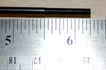
Slide the feathering shaft through the flap dampers. Get it
more or less centered.
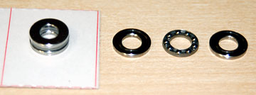
The thrust bearings are shrink wrapped because they
are actually three pieces each.
The two outside bearing races are not
the same size but you can't tell just by looking. Pay attention to
what you're doing here because this is the one place where it's easy to go
wrong.
Slide each race on the feathering shaft.
Wiggle it to find which one has a larger hole. One of the races will wiggle much more than the other.
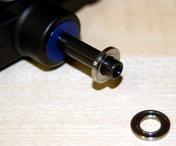
The
race with
the larger hole goes to the inside. The race with the smaller
hole goes toward the blade.
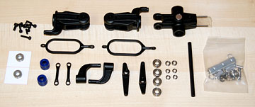
The main rotor pitch housing and associated parts.
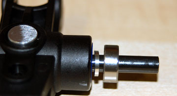
Slide the aluminum flap collar onto the feathering
shaft.
Slide on the bearing, flybar control rods and then the main rotor pitch
housing.
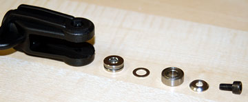
These are the parts that go inside the main rotor pitch
housing shown in the order they are inserted.
The first part to
go in is the thrust bearing. Again, make sure the larger hole
is in and the smaller hole is out.
After the bearing is inserted, slide on the thin flat washer
followed by the bearing and then the tapered flat washer.
Put a small amount of Loctite only in the feathering shaft. Thread
the bolt into the end of the feathering shaft to hold it all in place.
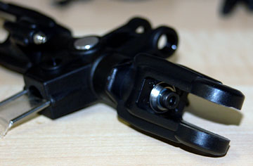
Place a hex wrench in each of the main rotor pitch housing
bolts and tighten them securely.
I didn't put the flybar control
rods on and had to remove the main rotor pitch housings so they could be
added.
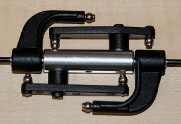
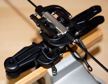
The main rotor pitch housings assembled to the main rotor
hub.
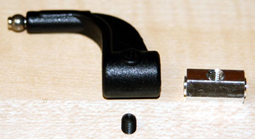
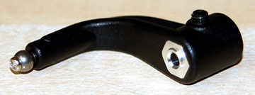
Parts for the flybar control arm.
Slide the flybar arm bushing into the flybar control
arm. Thread the set screw in a few turns.
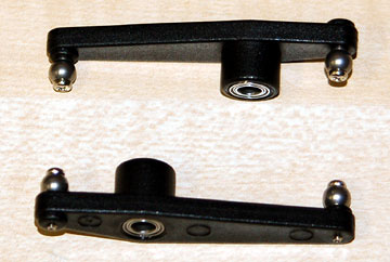
Insert a bearing into each side of each mixing
lever.
Thread two balls onto each lever.
Parts to assemble to the flybar seesaw hub.
Note the washers between the mixing levers and the seesaw hub.
Carefully center the flybar rod in the flybar seesaw
hub.
There is flat on each side of the flybar rod for the
set screws in the flybar control arms to tighten against. Ensure
they are lined up correctly before tightening them.
Check that
the flybar rod is still centered.
Add Loctite to the bolts for the mixing levers and bolt the mixing
levers to the seesaw hub.
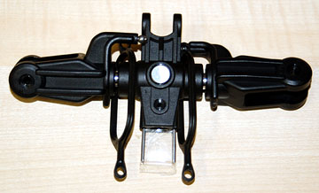
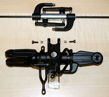
The seesaw hub assembly and main rotor hub assembly.
Add Loctite to the two bolts holding the seesaw hub to the
main rotor hub and bolt these assemblies together.
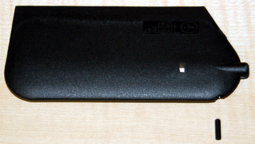
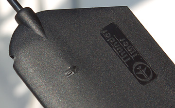
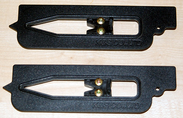
A set screw threads into the front of each flybar paddle.
Thread the set screw in several turns.
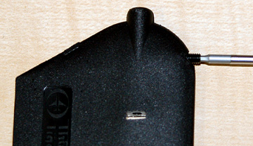
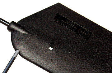
Thread the paddles onto the flybar rod until the end of the
flybar rod appears in the window cut-out in the paddle.
Measure the distance from the seesaw hub to each paddle to
ensure they are exactly the same distance
The paddles are very difficult to adjust with any degree
of accuracy due to the very tight fitting threads.
I suggest you thread the paddles on as far as they go
and then thread them back completely off at least three times to loosen
them up a little.
When you thread them on the last time apply a little
sewing machine oil or grease to the threads.
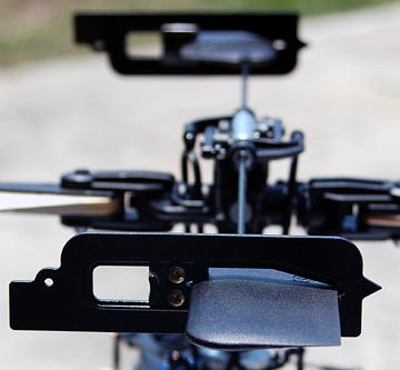
The rotor head turns clockwise. Ensure the paddles face the
correct direction.
A pair of paddle pitch gauges used to ensure the paddles
are absolutely level with each other. These do not come with the
kit.
The paddles should be level with each other and with the
swashplate when the swashplate is level.
This is
why you need to loosen the threads. If you don't, then when you try
to make minute adjustments to the pitch of either paddle, the flybar rod
will twist instead of the paddle turning. It suddenly lets loose and
the paddle ends up at some angle other than what you want.
When you are satisfied with the set up, tighten the set
screws in the paddles. Don't over-tighten them.