 |
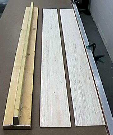
Before doing anything else, select the wood to
use for the fuselage sides. I like straight-grained wood that is
firm and light. Contest balsa can be pulpy so I generally do not use
it here. This model is receiving a
natural
finish so I also selected pieces that have a nice mottled
appearance and matched the overall tone of the wood. In fact, I
sorted the wood by color first and found that I had five different stacks
by the time I was finished.
I went through each stack until I
found three pieces of wood (sides and top) that matched in color,
grain-pattern, weight and flexibility.
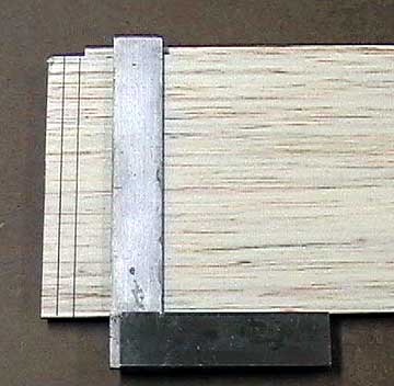
After the two sides each have one
true edge, locate the
reference line. Normally it will be parallel to the trued edge.
In this case I will use the bottom of the fuselage as the reference line
so another line is not necessary. |
 |
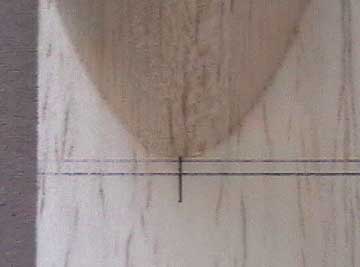
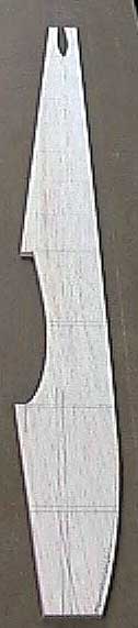
This is one of the original fuselage sides
that was scrapped. I have drawn in the firewall location.
The
thrust line will be 0°
right and 0° down (0°-0°),
so it is perpendicular to the bottom of the fuselage having no right or
down thrust. The new set of
fuselage sides has the
cowl as part of the side so the firewall is
located further back. |
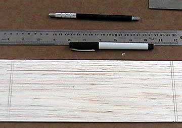 |
Next I measure back to the
leading edge of the wing. Normally I determine where the leading
edge is by measuring the
fuel tank length and adding 1/2" to 1" to that
measurement.
Measure the
chord of the
wing without the
ailerons and draw the location of the
former aft of the
wing.
Locate the wing centerline.
I normally set up a symmetrical wing with a very slight amount of
positive
incidence. This is because at 0°
the wing has zero lift. When I say a slight amount of positive
incidence, I'm talking about the leading edge being about 1/32" higher
than the trailing edge. In this case, that amounts to a fraction
of one degree. |
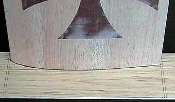 |
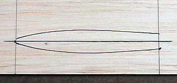
Carefully locate the wing
over the centerline and trace around it.
Now you can see why I have
left the wing tips off. Once the
saddles are cut (and you are sure
you will not be cutting another set of fuselage sides) the tips can be
glued on the wing. |
 |
Here you can see the leading edge of the
wing located over the centerline drawn on the fuselage. |
 |
Ditto for the
trailing edge of the wing. |
 |
The same method was used to locate the
cutout for the
stabilizer which was built up using a method similar to
the wing. |
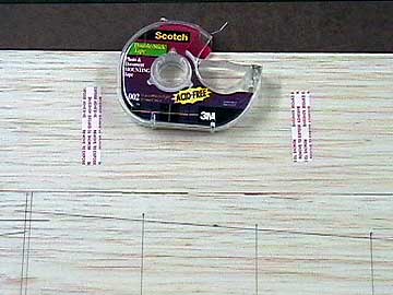 |
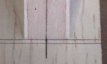
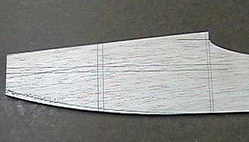
Thin fuselage sides tend to take on a
concave shape (the middle caves in) when the tail is pulled together.
To prevent this I glue vertical support pieces in the
aft end of the
fuselage. The lines drawn here represent the locations of these
supports. Their weight is negligible, but they really help keep the
fuselage sides flat. The fuselage
sides are taped together using double-sided tape. Cut the sides
and sand them carefully to shape while ensuring the edges remain square.
Leave the sides joined and transfer the
former locations to the edges of the sides. These lines are used
to mark the former locations on the fuselage side that has not been
marked. |
 |
The fuselage sides are carefully cut out
using straight edges and a scroll or jig saw. Because this model
will receive a natural finish I took extra care cutting the wing and
stabilizer saddles. Using putty and filler will not be an option
so the fit has to be good. I made a
sanding block from a scrap of 3/8" x 1-1/2" x 6" balsa. One of the
faces was gently rounded over and fine sandpaper was used to shape the
saddles after they were initially cut oversize. The wing and
stabilizer were checked against the saddles several times during the
shaping process. |
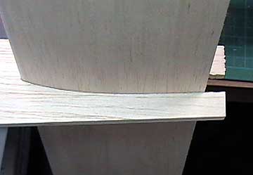 |
Here you can see the final stabilizer fit.
The excess wood aft of the trailing edge of the stabilizer will be
trimmed
away later. |
 |
After the thrust line was initially drawn
it was relocated 1/4" lower to position the engine properly in relation to the fuel tank. |

