Making the Cowl Cut-outs
The
engine should be
mounted before you begin. It is very important the cowl matches
the engine and not the other way around. If you mount the cowl and
then match the engine to it then the
thrust line will probably be fairly far off.
After the engine is mounted take careful measurements and mount the cowl.
If I can
disassemble the engine to a point where the engine can remain mounted
with the cowl slid over it then that's what I do.
Normally engine disassembly means removing the muffler, needle valve or the
entire
carburetor and possibly the engine head. The cowl is aligned
properly and then securely taped in place.
Whatever mounting holes are drilled and the cowl is screwed in place.
Hopefully it all comes out aligned properly.
Now remove the cowl and you're ready to get started.
There are normally up to four engine cut-outs that must be made.
- Muffler
- Main needle
- Idle needle
- Glow plug or possibly the entire engine head
Both needles must be accessible in order to adjust the engine.
The main needle may be long enough to reach past the cowl. If not
then most needle valves have provisions to mount an extension so the needle
can be adjusted with the cowl in place.
The idle needle normally won't extend beyond the cowl and does not have a
built-in way to extend it. Most commonly the idle needle is adjusted
by putting the proper driver through a hole in the cowl. If this is
the case then do not make idle adjustments with the engine running unless
you like bloody knuckles.
In all cases, the needle cut-out is usually just a hole drilled large
enough to pass the driver or for the needle to pass through the cowl without
touching it.
If the engine head interferes with the cowl then a larger cut-out must be
made to clear the cowl. If the head is fully enclosed then you can use
a remote glow plug adapter or cut a hole in the cowl to attach the glow
igniter.
Except for scale models with fully enclosed mufflers, almost all cowls
need a cut-out for the muffler. This article demonstrates how to make
the muffler cut-out.
Other cut-outs may be necessary for cooling air to enter and exit the
cowl. Many times the cowl is molded in a way that makes it obvious
where to make these cut-outs and no template is necessary. Other times
you may need to make templates from patterns on the plans.
Normally all cut-outs are made before the cowl is finished. In this
case I'm making cut-outs in a pre-finished cowl for an ARF.
 |
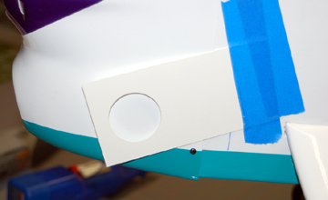
Mount the engine to the aircraft. Make a template for
each cut-out you plan to make. Always leave plenty of clearance
around items that extend past the cowl. If anything touches the cowl
it can cause all kinds of problems such as excess vibration, inconsistent
engine runs or a cracked cowl.
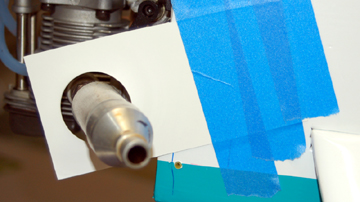
Align each template and tape in place as shown. |
 |
Remove the engine and mount the cowl. Do not remove
the template. |
 |
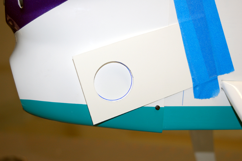
Use the template to mark the cowl. If the cowl is
unfinished then a fine point Sharpie marker works well. If the
cowl is finished then you might want to use something that can be
removed easily without damaging the finish.
My plan was to cut away the opening to the outer edge of the marker
so the marks would go away during the process. |
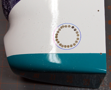 |
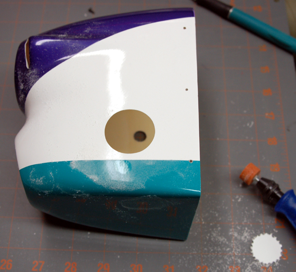
Remove the cowl. Drill lots of
holes around the inside perimeter of the opening.
Connect the holes with an
X-Acto knife or a cutter in a
Dremel.
Don't use a method that you can't control or you may have a mis-cut
which will either be ugly or require you to make the cut-out even larger
to hide the mistake. |
 |
Finish the cut-out using whatever method is appropriate.
A piece of
sandpaper wrapped around a dowel works well but takes a while.
If you use a Dremel then a garnite bit is an excellent choice for two
reasons. It is very unlikely to suddenly cut into the fiberglass
as a high-speed steel cutter might and it makes the edge much smoother
than cutters.
Use a piece of fine sandpaper wrapped around your finger to finish
sand the edge smooth. |
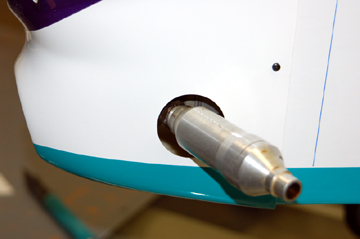 |
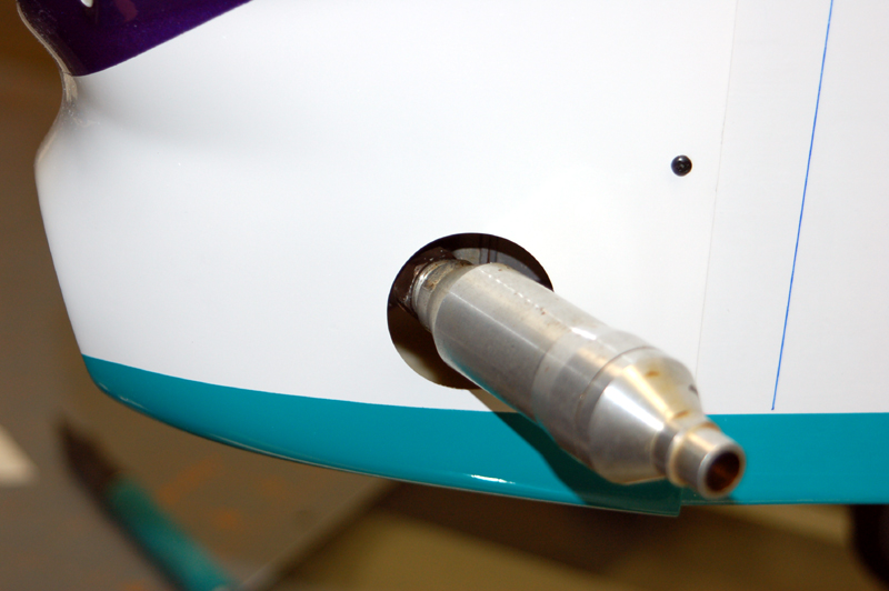
Along with being a muffler exit, this cut-out doubles as
a cooling air exit. This setup requires the muffler to be off
the engine when the cowl is attached. The muffler is then attached
to the engine and tightened.
I don't have this model any more and I honestly can't remember what
method I used to tighten the muffler. But I do remember that it
could be tightened securely so there may have been a cut-out underneath
the cowl that allowed a wrench to be inserted. |
|