Airfield Models - Installing Robart Hinge Points

Install Robart Hinge Points in a Model Airplane

December 19, 2021


Home
About
What's New
History
Models Gallery
Model Building Safety
Articles
Mail & FAQ
Site Map
Site Feedback
Contact
Add to Favorites
Comments
Search Airfield Models

Back to Robart Hinge Points


Airfield Models (http://www.airfieldmodels.com/)Use a Drill Press to Install Robart Hinge Points in Stick-Built Control Surfaces

In the following sequence, I am building a new rudder for Gonzo.  The original rudder was sanded extremely thin and warped badly when the covering was shrunk.  Attempts to correct the warp using heat just made the problem worse.

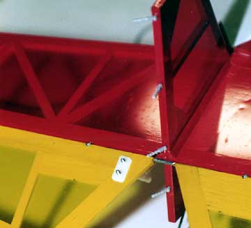
Because the rudder was more than big enough I cut the top section off the original rudder which is the white "bandaged" area.  To this day, I have no idea why I used white covering, but it always looked like a Band-Aid.

Not too long afterward, I managed to crack the rudder trailing edge when I was taking Gonzo to the flying field.  I did not think I could make an airworthy repair to the existing rudder so I decided to build a new one.
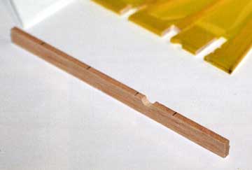
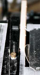
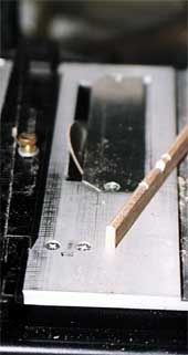
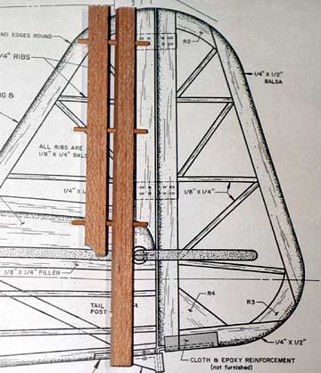
The fin and rudder are 3/16" balsa.  The hinges, Robart 1/2A 
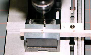
Hinge Points, require a 3/32" hole to be inserted into. That leaves only 3/64" on either side of the hinge.  A drill press greatly simplifies this task due to its precision.


Gonzo uses 1/2A hinge points.  Here the broken rudder has been removed leaving the hinges undamaged.

The first step is to separate the rudder from the fin.  I used a saw bit in my Dremel tool and left quite a bit of material attached to the hinge so there was no danger of cutting into the hinge and damaging it.

The excess material has already been removed from the hinges in this image.

It takes a bit of picking with an X-Acto knife to remove the remnants of the rudder from the hinges.  Epoxy does not stick to the plastic used in the hinges, but the barbs are tenacious.

A new rudder leading edge.  Hinge locations are carefully tranfered to the new part.

After the hinges are clear of old glue and wood use the hinge locations on the fin to mark the hinge locations on a new rudder post.  The larger cutout is to clear the elevator joiner.

Although the old rudder is shown here, do not use it as a reference for the hinge locations.

A drill press is the most accurate way to drill the holes, but is not the only way.

The hinge locations correspond with cross-members in both the fin and the rudder.

Drill the hinge holes using an appropriate size bit in a drill press.  A vise allows you to slide the rudder post to the next hole location without worrying about the holes remaining centered.

Alternatively, a scrap wood can be temporarily glued to the bed to use as an alignment device and pop it off when you are finished.  Wax the bed first to make removal easier.

A round file is used to enlarge the area for the hinge pivot point.

Use a round file to make the notches for the hinge in the post either before or after the leading edge is beveled.

   A table saw can be used to cut the bevel at the leading edge.  A razor plane and/or sanding block works as well but takes a little longer.

I use my table saw to cut a bevel on the leading edge of the rudder.  The leading edge can be planed and sanded to shape instead.  The table saw is faster and more accurate.

Hinging is now complete except for actually gluing them in.  This method is much simpler than hinging after building the control surfaces and if a mistake is made, the part can be replaced if necessary rather than trying to salvage the entire component after it is built.

The hinging process takes less than an hour not counting the time spent extricating the original rudder.

You will save a lot of time by doing all the hinging at the same time so you only have to set up your tools once.

The rudder leading edge is checked against the fin for fit to the existing hinges. Shown here is the finished rudder post prior to being trimmed and glued in place.  The post will be trimmed to length when building the rudder.
The completed rudder assembly. The rudder is completely built.  The previously drilled holes in the leading edge are used as a guide to drill into the cross members as far as necessary.  Whenever possible, locate hinges so they are fully enclosed by wood.

Always ensure there is enough wood to fully enclose the hinge.  If necessary, glue pieces of scrap wood behind the leading edge or in front of the trailing edge.

The extra wood will prevent the glue from being pushed through the hole into the surface where it does no good.

It is possible to do all the hinging before building.  Then use hinge blanks (dowels for hinge points or 1/32" plywood for flat hinges) to keep the parts aligned during assembly.

I used the same method to construct the tail feathers for my Sig Smith Miniplane.  The plan calls for only two hinges, but I have decided to use four instead.  The fourth hinge goes into the fuselage in the tail post.

The above steps have been completed and the parts are aligned with 1/8" dowels.

A problem with hinging after building the surfaces is that if the hinge slots or holes are even slightly off-center, the control surface will be offset to one side of the fixed surface.

Using dowels keeps the surfaces aligned throughout the building and sanding process.  If you are using flat hinges, then cut hinge blanks from 1/32" plywood.


Previous —
Next —

Install Robart Hinge Points in Sheet Surfaces
Hinge Point Sandwich Technique

Comments about this article


Back to Robart Hinge Points
Airfield Models Home


Copyright © 2002 Paul K. Johnson