|
|
|
|
Plotting and
Drawing an Airfoil
This is the third and final installment of this series.
Part 1 of this series provides some background,
explains coordinate standards and provides sources for obtaining airfoil
ordinates.
Part 2 explains how to calculate the ordinates that
are absolutely required before the airfoil can be plotted. This part
provides a details how to plot the ordinates on paper and then draw the
airfoil. |
|
|
|
Plotting the Airfoil
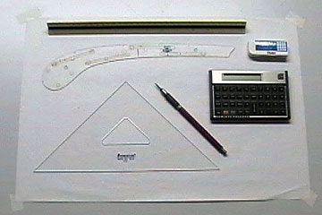 |
An airfoil can be drawn with a minimum of drafting
instruments. You
will need a sharp pencil, accurate scale (ruler), and a good curve. I use
ship curves because they better match the shape of an airfoil. French
curves are more common, but tend to have curves that are too sharp.
If you do not want to buy ship curves then an adjustable curve might
work. I've tried few different types of adjustable curves and none
of them were satisfactory to me. Your results may vary. If you must use French Curves, try to find one that is at
least twice the length of the airfoil you are drawing. You can also
bend a stick of wood which is surprisingly accurate. I use a piece
of 1/8" x 1/4" spruce to draw long curves, such as fuselages, when I draw
plans. The calculator only needs to be able to multiply, so any
calculator will work. |
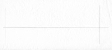 |
Draw a centerline slightly longer than the
airfoil chord. Draw lines to represent the
front of the leading edge and the rear of the trailing edge.
The chord of this airfoil is 9" so that is the distance the lines are
spaced. |
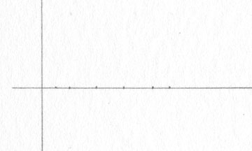 |
Make tick marks along the centerline to indicate the
station locations. The intersection of the
leading edge and centerline is point (0, 0) for this ordinate standard.
Some ordinate standards have the trailing edge as point (0, 0). If
you aren't sure what standard you're using, just plot the points.
If you are using the same standard as I am here, the airfoil will point
to the left.
If you plot the points backwards, the airfoil will point to the
right. Either way you end up with the same airfoil. |
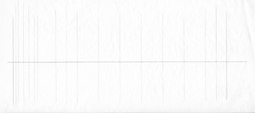 |
Draw vertical station lines through the ticks you
made in the previous step.
If the stations are different for the upper and lower
portions of the airfoil then you should probably make ticks for one
side. Then draw the lines. Repeat for the underside of the
airfoil. |
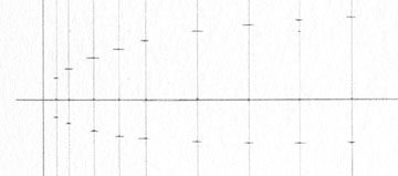 |
Tick off the ordinate locations at each station.
The trailing edge
of this airfoil tapers to 0" thickness. However, I will sheet this wing with 1/16" balsa.
That means I will have to fudge the airfoil somewhat to
account for the sheeting. |
The next image actually represents two steps combined
into one. I neglected to scan the drawing between steps.
 |
Draw the slope of radius through the leading edge.
Slope =
Rise over Run = y divided by x. In this case the Slope is 0.1.
To draw
the slope line, start at point (0, 0). Measure back 1" (x)
along the airfoil centerline and
from there measure up .1 inch (y). Draw a line through point (0,
0) and the point you just marked.
The center of the circle representing the leading edge is found on
the slope line by measuring from point (0, 0) to a distance equal to the
radius of the leading edge.
For example, if the diameter of the leading edge is 1", then
measure back 1/2" (radius) along the slope line. That is the
center of the circle that represents the leading edge. Draw the
circle.
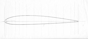
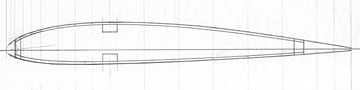
Using curves that match the point best, draw the
airfoil outline. Normally I use several different curves by
selecting the curve that best matches the airfoil in any given section.
The airfoil is tangent to the leading edge. |
Because of the thickness of the sheeting, it is not possible to draw the
exact outline through the plotted ordinates. However, the finished
product will be close enough that in our realm, nobody would notice the
difference in the flight characteristics.
Be as accurate as you can but do what needs to be done to make the wing
something that can actually be built and not just a theoretical ideal. |
|
|
|
Establishing the Rib Pattern
The airfoil outline is complete but it can't be used as is. The actual outline will not be
a part of the pattern unless the wing has no sheeting.
What we need to do is subtract the thickness of the
sheeting from the pattern and draw the location of structural details such as the
Leading Edge, Sub-Leading Edge, Spars, Ailerons and
Trailing edge.
The order in which you do these things in does not matter
as long as you know what's what.
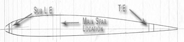 |
In this example, the Leading and Trailing Edges are 1/4"
wide. The Sub-Leading edge is 1/8" wide and the Main Spars are
3/8" wide. The Aileron is 1-1/4" wide. Main
spars are located where the wing is thickest for maximum
strength. |
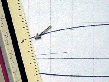 |
Work your way around the perimeter of the airfoil and
make tick marks inside the airfoil outline to indicate the thickness of the sheeting.
Arrange the scale so that it is
perpendicular to the airfoil at the point from which your are measuring
for best accuracy. I normally eyeball this, but better would be to
use an adjustable triangle that is adjusted to be perfectly tangent to
the airfoil at each point.
Make enough tick marks to draw an accurate outline. |
 |
Draw the rib pattern using the tick marks. The rib
pattern outline should be parallel to the airfoil. Finish any
other details necessary. If some ribs are different than others,
which is usual, then you should probably cut two patterns at the same
time.
For example, you may want to add landing gear cut-outs to the second
pattern. I usually draw
unique cut-outs directly on the ribs after cutting them out using a
single master pattern. Matching ribs from each wing panel are
stacked and cut at the same time. |
I tend to draw my pattern and glue it directly to whatever will
be used for the template. If you think you might want to save
the original drawing then make copies. Most copiers do not make
exact size reproductions
Copiers either enlarge or reduce from the original to a small degree. Usually it is by such a small
difference that it is not a
problem. Be sure to check before you start cutting patterns and ribs.
If the pattern off by an unacceptable amount you'll have a really bad
day if you find out that the wing you just built doesn't fit. Also see
|
|
|
|
|
|
|
|
Back to Plotting an
Airfoil
Airfield Models Home |
|
|
|
Copyright © 2004 Paul K.
Johnson |
|
|

