Airfield Models - Rebuilding My Stik 30

My Stik 30 Rebuild

December 18, 2021


Home
About
What's New
History
Models Gallery
Model Building Safety
Articles
Mail & FAQ
Site Map
Site Feedback
Contact
Add to Favorites
Comments
Search Airfield Models

Back to Rebuilding My Stik 30


Airfield Models (http://www.airfieldmodels.com/)The Tail Feathers

The last fin and rudder on the model were circular and not very attractive.  I made them after crashing the model and destroying the fuselage.  They were quick and easy to make but I never liked them.

The elevator and stabilizer were covered with Oracover.  Every time it was exposed to sunlight the covering would balloon like a pillow.  I ironed it down several times using various heat settings on my iron.  Nothing worked and it was an embarrassment at the field.


The old stabilizer with the new one. The old stabilizer with the new one.  Why I decided to go "3D" with it I have no idea.  I may be sorry I did it but I've already built 3 (this is the fourth) stabilizers for this model so building a new one won't be a big deal.

This is one of those Stiks that has the stab on the bottom of the fuselage so I just have to remember not to give full up when the model is on the ground or the counter balances will probably snag the ground and do some interesting damage.

At least I used enough hinges.

The new fin with the old fin. Time to get rid of the old ugly fin.  I always hated it so I used the CorelDraw graphic for Rustik's fin and scaled it accordingly.
New fin and stabilizer in place on the rebuilt fuselage. The elevator servo was moved to the rear of the fuselage because the pull-pull setup on the rudder servo made it next to impossible to place the elevator servo next to it due to interference of the arms.  That meant spacing the servos farther apart and finding a new location for the throttle servo.

Moving the elevator servo to the rear of the fuselage eliminated those problems and also allowed me to remove a long pushrod which somewhat negates the weight gain at toward the rear of the fuselage.

The model was still slightly nose-heavy as well, so moving the servo was a good thing in a lot of respects.

Pull-Pull controls for the rudder and a short pushrod for the elevator provide positive control. I used 50 lb SpiderWire for the rudder pull-pull system.  It is very strong and hasn't stretched in over a month's flying.

The elevator servo provides very positive control and good centering.  I replaced the linkage shown here with one having an L-bend at the servo end and a 2-56 Dubro ball-link at the elevator horn.

The trailing edge of the elevator was scalloped for a more classic Stik appearance.

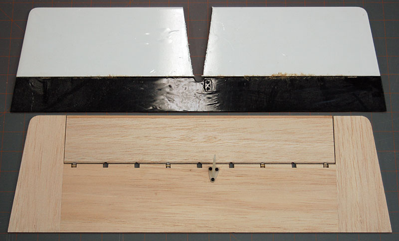
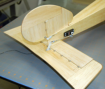
The trailing edge of the elevator has been scalloped for a more classic Stik appearance.

I cut away approximately 1/8" of the leading edge and tips of the elevator and laminated on a few pieces of spruce.  The weeds here play havoc with tail surfaces low to the ground and the sharp trailing edges are easy to ding.  I felt a little hardwood would minimize some of this stuff.

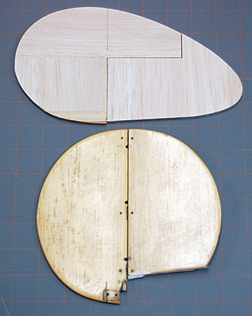
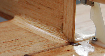
Unfortunately, I forgot to glue on one lamination so the leading edges of the elevator and stabilizer don't match.

Now that I've flown 
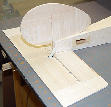
the model I've decided I don't like the 3D elevator/stabilizer.  The model only needs 1/8" up and down to fly very well.  Every time I 
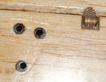
shoot a touch-and-go weeds get snagged between the counter balances and the stabilizer.

A fillet between the fuselage and stabilizer was shaped from balsa triangle stock. I used triangle stock to increase the gluing area for the stabilizer. 

The triangle was radiused and coarse shaped prior to gluing it on.  The fuselage and stabilizer were fiberglassed prior to gluing the stabilizer on.  The triangle was then glued in place.

It was shaped and finish sanded with my nifty fillet sanders.  Finally it was glassed with the cloth overlapping onto the fuselage and stabilizer.

Not visible is a piece of 3/8" sheet balsa glued between the fuselage sides above the stabilizer for additional gluing area and to sink dowels for the tail wheel bracket.

3/16" dowel hard points in the elevator to prevent the control horn from crushing the balsa. I drilled the elevator for 3/16" dowels to receive the control horn screws.  It's always bothered me watching the balsa crush when I tighten the control horns.

Without hard points the balsa would have crushed much more.  A lot of us have done it that way for a long time but I've never liked it.

I could have threaded the control horn screws into the hard points but I didn't trust them not to become fuel-soaked and let go.  For security I went ahead and used the control horn backing plate on the underside of the elevator.


Previous —
Next —

Rebuilding Between the Nose and the Tail
The Landing Gear

Comments about this article


Back to Rebuilding My Stik 30
Airfield Models Home


Copyright © 2006 Paul K. Johnson