Airfield Models - How To

Make Decorative Inlays for a Flying Model Aircraft

December 19, 2021


Home
About
What's New
History
Models Gallery
Model Building Safety
Articles
Mail & FAQ
Site Map
Site Feedback
Contact
Add to Favorites
Comments
Search Airfield Models

Back to How-To Articles


Airfield Models (http://www.airfieldmodels.com/)Make Decorative Inlays for a Naturally Finished Model Airplane

Something I have wanted to do for a long time is apply a natural finish an R/C aircraft that is fully sheeted.  I really like the look of wood and have seen very few models with natural finishes.  The ones I have seen were nicely executed and very attractive.

In some ways a natural finish can be forgiving of errors.  For example, low areas that would normally need putty will not show except under close scrutiny.  These areas would have to be filled for an opaque color finish.  Obviously the wood work needs to be good.  Gaps in joints and other poor craftsmanship will really stand out.

There are some obvious disadvantages to this finish.  Dings, dents and damage will be difficult if not impossible to repair to a like new state.  A break in the wood will be clearly visible.  One possible way to cover a repair would be to paint a trim color over the area.

Note: The inevitable happened.

RustikI decided to give it a try.  The worst thing that will happen is I will never want to do it again.  I originally was going to build a second prototype of Shadow and give it a natural finish.  I do not remember exactly when or why I decided to build Rustik, but somehow I just started building one and that is what is being presented here.

After making the decision to go with the natural finish, I began wondering what I would do for trim colors.  I considered several things such as staining the center sheet of balsa for the wing sheeting before joining the sheets and several other similar ideas.  Most of those ideas involved using stain.

I did not want to mess around with trying to stain balsa.  That would be akin to trying to stain a sponge.  I had nightmares of the sheet swelling to twice its thickness, warping so badly the sheet would be ruined or simply taking a month to dry.

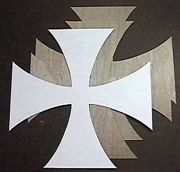
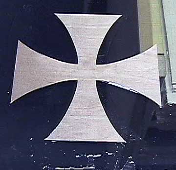
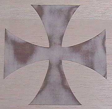
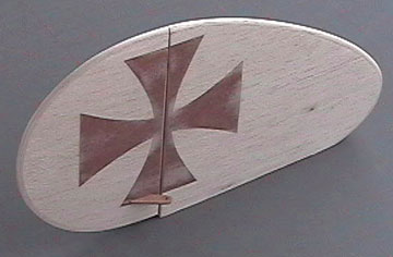
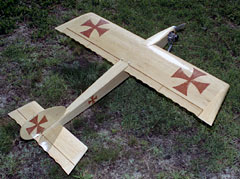
Then I had a brainstorm.  The classic Das Ugly Stik has large Maltese Crosses on each wing, the fuselage sides and on both sides of the fin and 
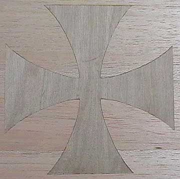
rudder.  It did not take me too long to figure out 
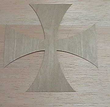
that I could inlay thin plywood into the sheeting.  The plywood is darker than the balsa and the finish would bring out the color.

This is the first time I have ever attempted any type of inlay other than simple rectangular plywood plates into control surface to provide a hard point for 
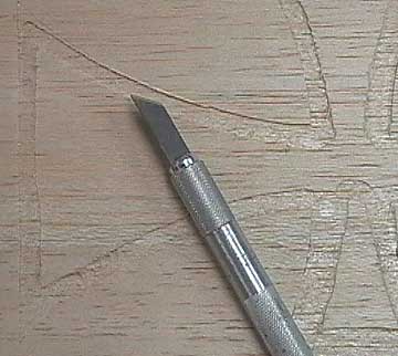
control horns.  Before ruining a lot of perfectly good wood, I practiced on some scraps to give me confidence that I could pull this off.

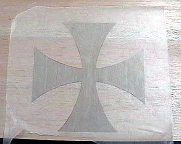
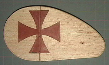
The sheeting is 1/16" contest balsa.  The Maltese Crosses are cut from 1/64" plywood.  A friend found some clip art on the web to use as a pattern and sent me the link.  The image was imported into a draw program and edited until I liked the shape.
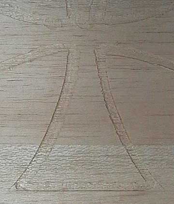
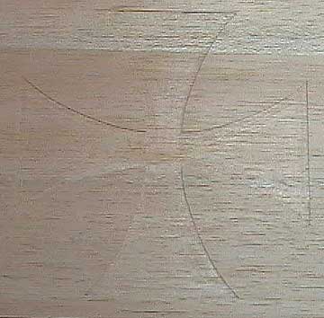
The finished pattern was too big for my printer so I cut the cross in half and added a centerline for registration.  Two copies were printed, cut apart on the centerlines and taped together to make a whole cross.  This pattern was spray glued to some heavier cardstock that was used as the final pattern.

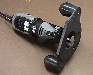
From the time I downloaded the image from the web to the time I had four plywood crosses was about two hours.  The time required to inlay the first cross was about 1-1/2 hours.  By the time I got to the fourth cross I was down to twenty minutes.  This is how I did it:


Making the Inlays

Before I got started I trued and joined three 4" wide sheets of 1/16" balsa for the wing skins.  The wing chord is 10" (without the ailerons) and the crosses are 8" square.

Maltese Cross Pattern and Inlays The cardstock pattern with two finished Maltese Crosses cut from 1/64" plywood.
Cut shallow outline in the wood to give a clean edge. I use a sharp X-Acto to lightly cut an outline around the cross.  Do not cut too deep. The purpose of this outline is ensure the edge will be sharp and a good fit.

The cut line allows me to stay a little farther from the edge so that a minor slip will not ruin the outline.  I find that when I route close to the edge without actually contacting it, the wood chips away up to the pre-cut outline.  Any wood that remains behind can be chipped out easily with a knife.

If you look closely you can see the outline lightly cut into the sheeting.  Be sure to mark the crosses so you know which one goes where and which direction it faces.

A router is used to remove wood for the inlay. A Dremel with the router base.  The largest bit I have is 3/16".  A real router could probably be used instead.  The Dremel router base works but it is poorly made.  The bottom is not flat and the poor excuse for a micro depth-adjustment has an unacceptable error tolerance.  It is difficult to adjust accurately.

Set it close to the right depth, loosen the collet and then pull the bit out slightly.  Set the base on two pieces of 1/64" ply with the bit resting on the workbench.  In theory the bit will be set at the correct depth.  Route some scrap wood to check.

The outline is routed first. Route close to the outline all the way around.  It is tempting to start cutting away the bulk of the wood, but do not do it until you've cut the entire outline.  The interior wood provides support for the router base.
The edge is cleaned up using a hobby knife. When the outlines are finished you can continue routing the interior wood or stop and clean up the edges.  I routed close enough to the edges that most of the wood chipped out to the previously cut line.

A few trouble spots remain as well as the corners that the bit couldn't cut into.  The blade shown here is great for getting into the corners.  I probably spent 20-30 minutes working on this.

Interior portions of the inlay are routed out. Remove the rest of the wood using a side to side, top to bottom pattern with the router.  I fit the inlay and found some areas that were not routed deeply enough.  This is mostly due to fuzz that did not cut cleanly and one corner I missed in the above step.

Scrape the entire inlay area with a single edge razor blade to smooth it out.  Several fittings may be necessary before the inlay lays flush with the balsa.

If anything I would have wanted it a little too deep.  I would rather sand the balsa to match the inlay than sand through a lamination of the plywood bringing it flush with the balsa.

Spread glue on a clean, non-porous surface. The next problem is deciding what glue to use.  Water-based glue is dismissed because of warpage problems.  Additionally, the inlay will be sandwiched between waxed paper which will slow down the drying process.

Epoxy is also a bad choice due to weight.  Spray glue hardens and crumbles after a year or two.  It is possible that eventually one of my planes will last that long so I have to use something else.

I realized I have the perfect glue — polyurethane.  It dries relatively quickly, is not water-based and it expands as it dries which is helpful because the routed balsa is not perfectly flat.

I poured a healthy amount on my glass building board and spread it out fairly evenly using a squeegee.

Place inlay in the glue. The cross is set in the glue.  Use something thin such as a single edge razor blade to lift an edge.  Ensure the entire piece is coated in glue so that edges do not come up later.
Inlay is placed into routed area and covered with wax paper. Place a piece of waxed paper below the balsa to prevent gluing the skin to the table in case any glue seeps through.  The cross is set into the balsa and another piece of waxed paper is placed over it.

A clean shop rag is placed over the waxed paper to provide padding.

Use weight to apply pressure to inlay while it dries. Gather items from around the shop that are heavy and can be stacked.  On the bottom is a piece of particle board.  Next is a toolbox, another board, some more tools, another board and a 12 volt deep cycle wheelchair battery.

I was going to put several gallon cans of solvent on the top board, but I thought better of it because the last thing I need to do is blow up my shop if the battery happens to short against a metal solvent can.

At this point I left it overnight to dry.

Inlay shown before sanding. This is the inlay prior to sanding.
Inlay after sanding. Remember what I said about making sure that the inlay is a little below the surface of the balsa?  This is my second attempt at it and I still managed to sand through the top lamination.  I decided that I would call it weathering or antiquing or something and live with it.

Originally I sanded through the lamination in two small areas.  I decided to sand away additional material to give it a more overall effect.  In fact, the more I look at it the more I like it.  But that may just be some genetic defense mechanism coming from my stone age, model-building ancestors that ensures I like what I build.

Umm.. what I mean to say is that I planned this effect from the beginning. People don't know you made a mistake unless you tell them.

Maltese Cross inlays in the fin/rudder assembly. This is the fin and rudder for the same aircraft.  The core is a built-up symmetrical section using ribs.

The 1/16" balsa skin was glued on both sides taking care to align them to each other.  The skins were allowed to dry, the outline was sanded and three laminations were glued around the edge.

After sanding the edges, the rudder was separated from the fin.  This procedure ensured the cross would be aligned perfectly on both the fin and the rudder.

The fin/rudder assembly after fiberglassing. The rudder and fin after being fiberglassed.

I am sure that routing the sheeting to accept the inlays significantly weakens the sheeting.  The addition of the inlays will make the wing heavier than necessary.  So there is a double whammy.  The wing does not entirely depend on the sheeting for strength.  The spars and shear webs will provide most of the strength.

Additionally, the crosses are placed towards the tips of the wing where strength is much less critical.  The bottom line is that I am confident the wing will be strong enough.  I would not do this type of thing on an aircraft that I wanted to be as light as possible nor would I put inlays in a strength-critical area such as the center of the wing.

After sanding through the laminations of two of the crosses I set the router to cut a little deeper.  That allowed me a little more room to sand and I managed to do so without going through the laminations as I had done previously.  However, I decided to go ahead with the look in the above photo, so I continued sanding until it had the same effect.

The problem here is that the laminations are 1/192" thick each (1/64" ply having three laminations).  There just is not much material there.  I think the real answer is to use a solid wood for the inlay instead of plywood.

Another way to do this would be to cut the inlay from balsa of the same thickness and then cut all the way through the sheeting.  The inlay could be stained and glued in place using Ambroid.  I can not say how well that would work having never tried it, but again, the most you have to lose is a few bucks in balsa and some time.

Now that the plane is finished, I can say that I am not a bit sorry that I did all this.  It was a lot of work, but I promise that you will not see a lot of planes like this at your field.  Most guys just are not willing to make the effort, so if you are, then you will have a very unique and beautiful aircraft.

Of course you can use any pattern you want.  I think a Chinese Dragon across the top of a cabin wing aircraft would be nice.  Look for simple line-art that will blend well with the lines of your aircraft.  Always keep in mind how much strength the sheeting needs to have.

As far as weight goes, Rustik, the plane having these inlays, came in at 4-3/4 lbs with 600 inches of area certainly not overweight.


Previous —
Next —

How to Build an All-Wood Landing Gear
How To Make Balsa Wood Plywood

Comments about this article


Back to How-To's
Airfield Models Home


Copyright © 2003 Paul K. Johnson