![]()
|
|
|
|
|
|
|
|
|
|
|
|
|
|
|
|
|
About the SR Batteries X440The SR Batteries X440 is nearly a perfect model airplane. There was almost nothing about it that I didn't like and nothing that I would change. I have to wonder what the heck is wrong with SR to have taken this gem of a model airplane off the market.
The X440 is a motor glider that will be at home at the average gas club site. It should not be flown in a confined area because it is light, efficient and should have a long glide slope. You won't be able to get it down without keeping it in a tight turn which isn't a good way to land. Please fly in an appropriately large area to help avoid hitting people and objects we shouldn't be even close to hitting.
|
|
|
AssemblyI followed the instruction sequence because I didn't want to make mistakes doing things "my way" and then find out later on that the instructions are in a certain order for a reason. V-Tail (Ruddervators)The all-wood, pre-covered V-Tail is called Ruddervators in the instructions. Either name is correct but I think V-Tail has a more elegant sound to it so that's what I'm going with. The factory makes good use of small balsa reinforcements to make the tail very strong without adding noticeable weight. The wood joints are perfect and these surfaces were dead flat. I checked the fit of the V-Tail in the aluminum tubes that are pre-installed in the fuselage just to see if there would be any problems. Not only did they slide right in, but they also have just the right amount of "snug" to keep them from sliding out on their own. This is the kind of work that requires careful jigging. When checked later, the V-tail aligned properly with the wing when viewed from the front and the rear. The instructions don't mention whether to glue the V-Tail in place, but I chose not to because it wasn't necessary. It wouldn't be a bad idea to put a few very small spots of silicone adhesive along the root. That will prevent the tail from coming off while allowing it to be easily removed when desired. Too much adhesive will shift the CG too far rearward. The one place where I didn't follow the instructions was when I hinged the V-Tail. The instructions made it a little more difficult than it really is. The surfaces are top-hinged using mylar tape. I trimmed 1/8" off each edge of the mylar tape because it is 1" wide (much more than necessary) and the edge was ratty. I would think 1/2" wide tape would be plenty. I then drew a centerline on the tape using a Sharpie. The surfaces were cleaned with Windex to ensure a good tape bond. Both the fixed surface and the moving surfaces are beveled. They meet at the top and are open at the bottom. I turned the parts upside down, closed the gap (down elevator), and then applied a couple pieces of low-tack masking tape to hold them in place. I then flipped the surfaces over so that I could apply tape to the top. I applied the hinge tape to the fixed surface first and then to the moving surface. I burnished it down with the edge of a piece of balsa and then trimmed the ends. ServosThe next thing to install is the servos and pushrods. The servo mounting system is ingenious and perfect for small, low vibration (and low impact) airframes. The servo rails have notches cut to receive the mounting ears of the servo. Webs must be cut away from the servo lugs or the rails can be modified to receive the webs unless the rails would be weakened too much. Rail supports and one rail are pre-installed. I ran a small bead of epoxy around existing joints per the instructions. The second rail slides in place and is screwed down after the servos are placed into the existing rail. Holes must be drilled in the wing saddle to allow passage of a screwdriver to mount the rail. Holes for the second servo rail must be drilled to receive the screws. Because the rails are in close proximity to the wing saddle, a good pair of eyeballs is all that is needed for good alignment. I had to modify the rail notches that accept the servos used because the mortises were slightly too wide. I split a toothpick sideways to fill one side of each mortise. The easiest way to install the carbon fiber tube pushrods is per the instructions. The included pushrods were dangerously close to being too short. There are enough threads to hold the clevis after lengthening it, but barely. One or two more threads and I would have been making new pushrods. The pushrod is connected to the V-Tail style control horns using helicopter ball-links. The instructions note to sand off the plastic shank where it meets the carbon fiber pushrod or it may get stuck on the back end of the fuselage when pulled. I used a sharp X-Acto chisel blade instead and kept turning the pushrod until there were no more raised edges on the ball link shaft. The pushrods are connected to the servo arms using threaded metal clevises with locking nuts. Both pushrods exit through the opening made by the aluminum tube "X" at the bottom of the fuselage. I noticed the balls mounted on the control horns clicked together at one point in the travel so I ground off just the outer edge of the ball on the screw head side. There is no danger of the link coming off and the balls miss each other. Motor and Speed ControllerThese were supplied already wired together as a unit. The motor is mounted inside the fuselage behind the firewall. It is deep within the nose so I thought it would be a very frustrating task getting the threaded holes in the gear box lined up with the pre-drilled holes in the firewall. The first thing I did was brush epoxy on the firewall from the front, per the instructions, and also from the back using a dowel in an acid brush. I waited for the epoxy to cure before moving along. The front of the motor is slightly raised so I test fit it from the front to ensure the engine shaft hole allowed the motor to pass properly. I had to ream the hole slightly to achieve a good fit. I held the motor by the wires and lowered it into the fuselage while holding it over my head so I could see if everything was lining up properly. I got it on the second or third attempt but it would probably be easier with two people. Once the motor was screwed in place, I test fit the folding-propeller/spinner assembly. Again, everything fit perfectly and the spinner is dead center in the nose. If it's off at all, I can't tell. The speed controller is mounted to the top inside fuselage nose using Velcro. Initial balance showed that the 7-cell battery would have to be mounted about halfway between the servos and the motor. I used Velcro to secure the battery. It is easily inserted and removed from the fuselage for the quickest possible pack changes at the field. ReceiverThe receiver is mounted on it's side behind the servos and between the pushrods using sticky-back Velcro. I taped the antenna to the top edge of the receiver using fiberglass packing tape to create a strain-relief. Because carbon fiber pushrods are conductive, I wanted to ensure the antenna had as little chance of contacting them as possible. I pulled the antenna through the rear of the fuselage opposite of where the pushrods exit. I pulled the antenna taut and used another small piece of fiberglass packing tape secured it. I used the round edge of a dental pick to burnish down the tape well. WingThe instructions indicate that the wing should be "flattened" before flying the model. The idea is that the wings may have picked up some slight warps or bows from the covering or for some other reason. This wing did have minor warps in the outer panels. One panel had wash-out and the other had wash-in. These warps were undoubtedly caused by the covering. This was the one thing wrong with the plane and it is pretty serious. When I received the model it was already fairly old and the covering had become somewhat brittle as evidenced by several small holes in it and the fact that I added several more doing things that would not normally puncture a film covering. I attempted to remove the warp with careful use of a heat gun but it didn't work and I didn't want to risk melting the covering. Had the covering not been so brittle I would have kept at it. In this case I think the only fix would be to replace the covering. The person I assembled this model for didn't want me to do this, but if it were my plane I would have removed the existing covering and recovered the panel. An aircraft with a warped wing will never trim properly. The wing construction is beautifully done being of all-balsa construction and having carbon fiber spars and leading edges. There was some balsa fuzz in the wing, but not much and I've seen far worse. The wing is two-pieces that come apart for storage and transportation. They join together using a carbon fiber tube/socket and two dowels for alignment. The dowels shaved themselves down to a perfect fit when the wings were joined for the first time. There are two mounting bolts to hold the wing to the fuselage. The bolts also prevent the wing from separating. The holes in the wings are counter-sunk for the included nylon pan-head screws. Again, it was unbelievable to me that the first time I placed the wing on the fuselage the holes in the wings aligned dead-on with the threaded inserts pre-installed in the fuselage. I expected I would have to sand the roots a little or possibly spread the wing slightly. I was wrong. All I had to do was thread in the screws and the X440 was done. I missed all the fun. FlyingUnfortunately, I did not have the opportunity to fly this model. Judging from it's areas and moments, I see no reason why it shouldn't be an excellent performer. Hopefully I'll receive a flight report from the owner.
|
|
|
|
|
|
|
|
|
Copyright © 2006 Paul K. Johnson
|
|

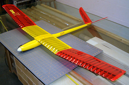

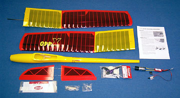 The model is Almost-Ready-to-Fly (ARF) having a gel-coated fiberglass
fuselage with built-up wings and tail. It is designed for electric
propulsion and a 3-channel radio with mixing.
The model is Almost-Ready-to-Fly (ARF) having a gel-coated fiberglass
fuselage with built-up wings and tail. It is designed for electric
propulsion and a 3-channel radio with mixing.