![]()
|
|
|
|
|
|
|
|
|
|
|
|
|
|
|
|
|
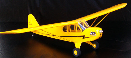
About the Herr Piper CubThis model was built for Joe, a fellow club member, who originally asked me to build a Bride of Gonzo. I had several builds in front of his and by the time I was ready to start on his Gonzo Joe instead presented me with the Herr Piper Cub kit and asked me if I would build it. I enjoyed building my Herr Pitts Special so I reasoned that this model would be equally enjoyable. This model was, in fact, a lot of fun to build. It is simple and straight forward. I was having so much fun building the Cub that I added all the included details even though I was told I could leave them off. For example, the kit is intended for a throttled 1/2A engine such as the Norvel .049 or .061. The engine is side-mounted so the kit comes with only one dummy engine for the other side of the cowl. Because I was building this one for a fully cowled electric motor, I elected to order the other half of the dummy engine kit from Sig for $5.00. The dummy engines build into a reasonable illusion due to nicely thought out engineering. Conspicuously missing from the kit is the Cub logo for the fin. I presume this is due to licensing costs. Along with the kit, Joe provided virtually everything that was to be installed including a set of fiberglass floats. Our club field is currently under water thanks to the two hurricanes that came through the neighborhood. Additionally, Joe lives by a lake so he felt it was time to have a seaplane. I have the feeling that Joe didn't really understand how small this plane is. The floats were very heavy. Between the floats and the power package the model's flying weight would have been approximately really overweight. The PJS 1000 out-runner motor is the same as used on Bride of Gonzo which is larger and heavier aircraft. Bride of Gonzo uses a 3-cell LiPoly pack, but Joe gave me a 4-cell pack for the Cub. Basically it would be way over-powered as well as overweight. Mike and I managed to convince Joe to switch to a 3-cell pack. My actual recommended power system would be the same AXI 2208/20 motor used in the BMJR Models Splash-E Seaplane that I completed prior to starting on the Cub. The AXI motor will provide plenty of power while lowering the overall weight and wing loading. Joe elected to stick with the PJS, but decided against the floats. To help counter the additional weight of the motor I did everything I could to keep the weight from building up and providing maximum leeway for battery placement so the plane can be balanced without adding ballast.
|
|
|
ConstructionOther than sticks and sheets, all wood components are laser cut. The entire model is built using Elmer's Carpenter's Glue. I began construction with the fuselage.
There is only one way the parts can mate together so this was clearly a manufacturing error. According to the directions the left and right sides are different to create right thrust. The lower fuselage piece is identical for both sides, but the upper two pieces differ from side to side (according to the directions). I tried mixing and matching the pieces with no luck. I contacted Sig who sent me replacement parts. The new parts had the same problem. I called Sig back and was transferred to voice mail and I never heard back from them. I have no idea if they have corrected the error or not. I ended up using two of the upper right sides which mated perfectly with the lower pieces. It is actually the forward pieces that establish the right thrust and these pieces fit fine. I did not have to modify anything and the fuselage sides came out as intended. The left side pieces are simply wrong and won't work as supplied. The instructions and plans may be wrong as well because using two right sides worked. The fuselage turned out straight with the proper amount of right thrust. All the formers fit with no modifications. Had I not received the new parts I would have had to cut new sides from balsa wood sheets. I left out the 3/32" square balsa window framing pieces that are supposed to be glued in place when the sides are built because they are small and fragile. I figured they would get broken at some point during construction so I glued them just prior to applying the finish. Various doublers are added to the interior of the fuselage sides. This completes the fuselage sides which are now joined with formers followed by the upper and lower sheeting. It's fairly standard construction. Even though the parts jig together it is possible to build a crooked fuselage. Take your time getting everything aligned before gluing it all together.
The servos mount through a hatch on the underside of the fuselage. The chosen servo location leaves the entire cabin available for battery placement to aid in balancing the model. I installed pull-pull controls using Power Pro braided fishing line as a weight-saving measure rather than installing NyRods indicated on the plan. The cabin is huge by the way. You can fit anything you want in there including a pilot. In fact, if you are inclined to you can add a lot of interior detail. Keep in mind that this model is not intended to be a scale masterpiece and doesn't even have ailerons. Keep the weight low and you will be rewarded with a nice flying model. The cowl was almost as bad as the cowl included with the Pitts except it is one piece instead of three. It had 2 or 3 large bulges and was very thin on one side. It obviously didn't get pulled over the mold properly. I fiberglassed the entire inside of the cowl to prevent it from cracking and especially to reinforce the thin side. From there I block sanded off the bumps taking care not to sand through the plastic. I then wet sanded the entire cowl reasonably smooth in preparation for paint. A couple drops of dark red Klass Kote epoxy paint were mixed with an ounce of yellow to get a fair match to the Oracover Lite Cub Yellow used to cover the model. This quantity of paint (approximately 2 ounces including catalyst) was plenty for the painted items which include the cowl, wing struts, wheel hubs, control horns, cabin interior and firewall. I did not use any primer on the model.
Covering was applied two days after painting. The Oracover adhered well where it overlapped onto the paint Heat from the iron did not affect the paint at all. Like the Herr Pitts, the Cub uses covering to attach the fairings to the music wire landing gear. Hopefully this one holds up better than the gear on the Pitts. The tail group is simple and straight forward. I cut control horns for the pull-pull system from thin aircraft plywood. The tail wheel wire is inserted into the lower part of the rudder. I have done this on many planes and have yet to have one break loose. I glassed the lower portion of the rudder to reinforce it. There isn't a lot of room on the rudder below the stabilizer so I cut a slot in a flat hinge to slide over the control horn. That allowed me to mount both the horn and a hinge near the bottom of the rudder. If I had not done that, the next closest location for a hinge would have been above the stabilizer which is too far away from the control horn to provide good support. If you use the control system setup shown on the plan you won't encounter this problem. The wing is simple and can be completed quickly. It consists of two outer panels glued to a center section. The center section is built first and then blocked up so that one of the outer panels can be built. When the first outer panel is complete, the process is repeated for the opposite panel.
There are braces on the front and rear of both the top and bottom spars - eight in total. This didn't present any difficulty and is strong enough, but I would still like a single brace better. I haven't been able to figure out the advantage of the two braces. The outer panels have two 1/8" square balsa turbulator spars on top of the wing near the leading edge. The trailing edge is 1" wide balsa sheeting on the top and bottom which I prefer to a solid trailing edge that is unsheeted. The supplied sheeting was badly bowed so I replaced it with wood from my stock. The root of the outer panels and the entire center section is sheeted as well. Again, the wing has no ailerons, but they can be easily added. Mike thinks the model should have them but I like three-channel models. I would build the kit for myself just as I built this one — sans ailerons. I sanded the fuselage to match the leading edge of the wing center section after the wing was mounted. This completed the basic assembly of the model. If you wanted to skip the detail work you could go straight to covering, install your equipment and fly. The Oracover Lite is very easy to work with and went around the curved edges of the model with no difficulty. It isn't as opaque as heavier coverings, but the model looks nice nevertheless.
After the parts were glued together I brushed on a coat of polyester resin. The cylinders were painted with Testor's Model Master black enamel that was lightened and flattened using a small amount of flat white. I had lightened the paint for my plastic models because black never looks right. For this model, pure black would be fine. The engine heads were painted with Model Master Chrome Silver.
Note that the enamels used are not fuel proof which wasn't a consideration for this model. If you use hobby enamels, but use a glow engine, be sure to spray a couple coats of clear fuel proof paint. The completed engines were glued to the cowl using black silicone adhesive. The wing struts are non-functional and simply plug in. They consist of 3/32" x 1/4" balsa struts with 1/16" music wire ends bent to an angle. The sockets are pieces of inner NyRod that are sanded to have a flat on one side. The sockets were CA'd to the fuselage and wing using medium CA after covering was removed from the area. Be sure to iron down the covering securely before cutting it and remove as little as possible. The windscreen was temporarily taped in place and then marked using a Sharpie fine point marker. Tamiya masking tape was used to mask off the area in front of the line so that the anti-glare area could be painted. I brushed on two coats of Tamiya semi-gloss black.
During the fitting process, I was struggling to get the windscreen to conform. I did not believe it would stay down for long once it was glued in place, so I used thinner material instead (.010" thick butyrate plastic available from K & S). This material is stiff enough to maintain its shape while being thin enough to glue down in the first place. Although the instructions state that the covering can be scuffed and have the windscreen glued directly to it, I didn't trust that to work. I removed the covering from the framing on the fuselage and painted it yellow and then glued to the paint. If you take your time with the windscreen and follow the directions you should have few problems. I cleaned up the lower windshield using 1/8" wide black pin-striping tape. The side windows were glued to the covering because they are flat and are not under the same type of tension as the windscreen. As a finishing touch I used a Sharpie fine point permanent marker to draw the cockpit door on the right side of the fuselage and the ailerons. To ensure consistency, I cut a template from cardstock for the ailerons and put a couple layers of tape inside the edge to raise the template so that the ink wouldn't bleed underneath. If you make a mistake, the lines can be wiped off easily using denatured alcohol.
|
|
|
Conclusion
With three mini servos, a light receiver, battery and the recommended power, this plane would have come in at or below the recommended weight of 19 ounces. As of this writing the model hasn't been flown. I would test fly the model without the struts but then add them. If the wing were to flex much, I suspect the struts would break free, but the model is intended for gentle flying. The power package that is installed will make it easy to push the model beyond its limits, so I hope Joe takes that into consideration by using the throttle judiciously.
|
|
|
|
|
|
|
|
|
Copyright © 2004 Paul K. Johnson
|
|


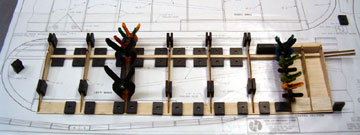
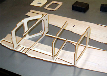 The fuselage sides are assembled from three pieces that key together.
This was the only problem in the kit. The left side of the fuselage did
not fit one of the mating pieces.
The fuselage sides are assembled from three pieces that key together.
This was the only problem in the kit. The left side of the fuselage did
not fit one of the mating pieces.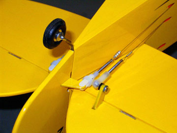 I assumed the model was designed to balance properly with the intended 1/2A
engine which is far lighter than the PJS motor. Therefore I modified the
model to place the servos behind the wing rather than in the cabin.
I assumed the model was designed to balance properly with the intended 1/2A
engine which is far lighter than the PJS motor. Therefore I modified the
model to place the servos behind the wing rather than in the cabin.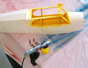 The interior of the cabin and all wood parts that would be visible through
the windscreen and side windows were sprayed using an Aztec
The interior of the cabin and all wood parts that would be visible through
the windscreen and side windows were sprayed using an Aztec
 The dihedral braces are different than anything I've ever seen.
Rather than having a single piece go through the center into the outer panels,
the design uses two braces that meet in the center.
The dihedral braces are different than anything I've ever seen.
Rather than having a single piece go through the center into the outer panels,
the design uses two braces that meet in the center.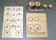 I went ahead with the non-functional stuff just because it was fun to do.
The dummy engines consist of several balsa rings that slide over a 1/8" square
post. It is easy to build and adds a lot of character to the model.
I sanded the exhaust pipe as round as I could considering it has a rectangular
cross section. I also rounded over the engine heads.
I went ahead with the non-functional stuff just because it was fun to do.
The dummy engines consist of several balsa rings that slide over a 1/8" square
post. It is easy to build and adds a lot of character to the model.
I sanded the exhaust pipe as round as I could considering it has a rectangular
cross section. I also rounded over the engine heads.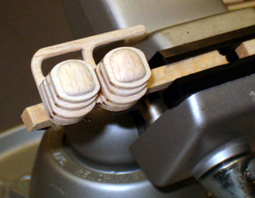 After the paint was dry I mixed up some gray oil paint
and dry-brushed the cylinders. The dry-brushing did a little to add contrast, but
because I didn't spend a lot of time sealing the wood grain and sanding to a
grain-free base, the effect was somewhat diminished. Nevertheless, I like
how it came out and feel it was worth the amount of effort I put into it.
After the paint was dry I mixed up some gray oil paint
and dry-brushed the cylinders. The dry-brushing did a little to add contrast, but
because I didn't spend a lot of time sealing the wood grain and sanding to a
grain-free base, the effect was somewhat diminished. Nevertheless, I like
how it came out and feel it was worth the amount of effort I put into it.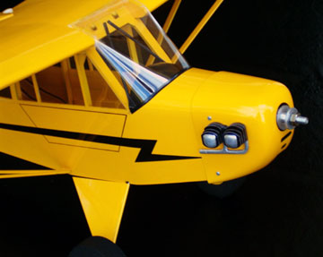 A large sheet
of plastic is supplied for the forward windshield and side windows. A
template for the windscreen is provided on the plan and is slightly over size
allowing for trimming to a good fit. The plastic is very thick for a model
this size.
A large sheet
of plastic is supplied for the forward windshield and side windows. A
template for the windscreen is provided on the plan and is slightly over size
allowing for trimming to a good fit. The plastic is very thick for a model
this size.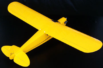 Finished
weight of the completed structure including covering and paint but without the
flight pack or propulsion system was 12.7 ounces.
Finished
weight of the completed structure including covering and paint but without the
flight pack or propulsion system was 12.7 ounces.