![]()
|
|
|
|
|
|
|
|
|
|
|
|
|
|
|
|
|
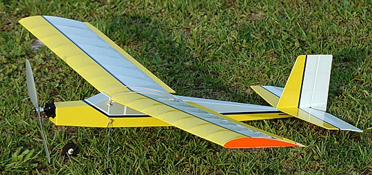
About the Great Planes TutorThe Great Planes Tutor is a lightweight, balsa structure electric park-flyer. The instructions are well written and very detailed. The plan is also excellent. All wood components are accurately laser cut. Most of the wood was good quality, but some parts were discarded for reasons to be discussed. I do not recommend this kit to beginning builders because it is very delicate and easy to damage while building. The wing is very flexible and likely to be warped when the covering is applied. If you don't have much experience then it is a good idea to enlist some help when it comes time to cover the wing. Experienced builders should have no problems with the build and when completed the airplane will be something fun to putter around a small field close to home. Beginning pilots should have an instructor help them learn to fly. This model can be used as a trainer, but again, it's delicate and will probably be destroyed with any significant impact. An instructor can help get the model up and down safely while you learn to fly.
|
|
|
ConstructionTail Surfaces
The hinges are regular scotch tape that is adhered to the covering. This system works but it's sloppier than "proper" hinges. I wanted to prevent introducing more play into the system by giving the covering more wood to bond to. The stabilizer center section is made up of three 1/8" square balsa sticks. I don't know how Great Planes expects you to do this, but the fin is 1/8" thick which means you will have to remove all the covering from the center stick in the stabilizer to glue on the fin. That will leave the covering just flapping on either side of it until it gets to the next stick. The other option is to remove less than all the covering making a precarious mount even more so. Instead of dealing with that I simply made a solid center section for the stabilizer. Do yourself a favor and replace the 1/8” square fin root with 1/8” x 1/4" medium balsa. If you use 1/8” square balsa it is very likely that it will bow inward when the covering is shrunk which will make it difficult to obtain a good glue bond when it comes time to attach the fin to the stabilizer. The last modification I made was to add several 1/32” reinforcing gussets. These modifications made an insignificant difference in weight and did not affect the balance. Fuselage
The pushrod exits are accurately marked on the plan but not cut into the sides. This seems like another missed opportunity. What actually bothered me the most was that both sides had undulations from the sheets being sent through a board sander. The undulations were so extreme they could not be sanded out without making the sides too thin. If you look closely at photos in the gallery you should be able to see vertical lines on the fuselage sides from the sander.
The instructions indicate a different position for the rear wing dowel if ailerons are utilized. The alternate position is a better position whether or not ailerons are used. Be sure to drill the new holes before gluing anything to the sides. Tape the sides together to ensure the holes are accurately located in each. I plugged the original holes using a balsa stick that I pulled through a hole gauge to turn it into a dowel. I added a piece of balsa across the grain of the fuselage side to reinforce the rear dowel in the new position. The front dowel glues to a former and didn’t need any modification. The dowels were added after the fuselage was completely built. After sliding them in place I secured them with thin CA from the inside so that it would not fog the covering. Thin CA was used so that it could harden the balsa around the dowel. The dowel mounting is delicate as is the wing center section. The rubber bands included in the kit are too small and will unnecessarily stress the wing center section and dowels. I found that #45AA are a good fit. Only two rubber bands per side are necessary to safely secure the wing assuming the bands are in good condition. Using too many rubber bands will either crush the wing center section or damage the fuselage by pulling the dowels loose. A good source of excellent quality rubber bands in any size is the Dykma Rubber Band Company. I added a diagonal piece of 1/8" square balsa inside both fuselage sides from the firewall to former F2. This piece was added to stiffen the forward fuselage and prevent it from bowing in. I discarded all the laser cut deck sheeting. All the upper decking had the grain arranged at a strange diagonal although it was clearly supposed to run fore to aft. The lower rear decking also had the grain running fore to aft so I replaced it with cross grain sheet. The forward lower decking had the same weird grain as the upper decking so I also replaced it with cross grain. The hole in the firewall to receive the motor didn’t align properly with the pre-drilled holes for the gearbox. I used a drum sander in a Dremel to make the hole a little oblong until everything fit properly. Only two of the three mounting tabs on the gear box are used which allows the box to rock even when the screws are fully tightened. The plans show scrap balsa behind the firewall to provide additional material for the motor screws to bite into. This is a new one to me as I've never considered balsa to be a good material to hold a wood screw thread — particularly for a screw that is retaining a motor. I used thin plywood instead. Overall I don’t like the setup and think the model should be re-engineered to move the motor down such that the thrust line is lowered and the gear box can be mounted using all three screws. This change may require the fuselage to be deepened in the front. I haven’t measured it. Wing
If that doesn’t bother you then the advantage is that a dowel can be easily sanded in a minute before gluing it in place and there is no further shaping necessary. Shear webs are glued to the spars from the second rib from the root to about 2/3 of the span. There is no web between the root rib and the next rib because that is where the plywood dihedral brace is glued. The webs are glued to the back of the spars which is probably the easier way for a beginner builder to install them. I cut the webs to fit between the spars. As long as you obtain a good glue joint either way is fine. The wing tips are not pre-cut so you can do your own thing with them. I simply laminated a piece of 1/16" balsa to the tip rib and sanded it to match. I didn't want to mess around with trying to pull covering around a wing tip on a wing this flimsy. I probably would have broken half the ribs in the process. The ailerons are 3/4" x 1/16” balsa. These are very flexible and probably much less effective than they would be if they were stiffer. I considered various ways to make the ailerons more rigid but the only effective solution I could think of was to make them thicker. Building thicker ailerons would have meant removing about 3/8” to 1/2" of chord from the trailing edge of the wing for everything to flow together smoothly. The wing was already built having 1/32” trailing edge sheeting. I didn’t want to risk having the trailing edge sheeting break and have to replace it all so I stuck with the ailerons as designed hoping that the slow speed of the model would prevent them from flexing too much or from fluttering. The wing is adequately strong, but extremely flexible making it a challenge to not introduce warps when covering. All I can recommend is to be careful and work slowly when applying the covering. If you're a beginner then seek help before attempting to cover the wing by yourself. The plans call for washout in the wing. After the wing was covered but before the covering was shrunk, I weighted down the center and blocked up the trailing edge at the tip 3/8". I then use my covering iron to shrink the covering on the top of the wing. When that was complete I lowered the heat to the lowest setting that would still shrink the covering and shrunk the covering on the bottom of the wing. The result was about 1/4" of washout in each wing panel. Landing Gear
There are a lot of good landing gear designs that I think would have been better for this model. A simple V in the center clamped between two thin plywood formers or individual struts running across the bottom and up into torsion blocks inside the fuselage are both easy to make, effective and very reliable. The axles were cut too short for the included wheels. There simply wasn’t enough sticking through the wheel to attach the included nylon wheel collars. I drilled out the wheels and made longer axles using brass tube with a washer soldered on one end and a washer held in place by a wire at the other end. The new axle is held in place on the wire gear using permanent Loctite. The tail skid shown on the plan looks really fragile and precarious. It may work fine, but I didn’t trust it and made a wire skid instead. The skid is mounted to a piece of 1/32” plywood, wrapped with SpiderWire and coated with glue. Radio and Linkage InstallationWhile the radio installation is simple, the soft 1/16” aluminum tube pushrods are delicate and flimsy. Having an experienced helper when it comes time to install the radio and make the linkages will be beneficial to the beginning builder. I didn’t like the choice of much of the hardware included in the kit although the pack was very complete and can be used. While being somewhat expensive, I decided to use micro hardware recently released by Dubro. I used Dubro micro clevises for the elevator and rudder with Z-bends at the servo end of each pushrod. The instructions call for a Z-bend on both ends of the pushrod which means trim adjustments must be made solely from the transmitter. If you use the recommended system then you will not be able to adjust the pushrods so that the transmitter trims can be centered. I was asked to build this model for elevator, aileron and throttle. I went ahead and made the rudder functional so that it can be set up for use later. A “dummy” servo was cut from 1/32” plywood to attach the pushrod. This setup allows the rudder to be trimmed on the ground while being in a fixed position for flight. I also used the micro aileron hardware from Dubro with the addition of two more micro clevises. Attaching the clevises to the aileron horns while everything is flopping around is not something I would recommend attempting until after the Xanax has kicked in. The pin in the micro clevis is a separate piece. In the flight shots and possibly the video you will see a long section of antenna trails behind the plane which I'm sure affects its flight. For test flights I used a Hitec Micro 555 receiver because the receiver supplied to me for installation was not on the same frequency of my transmitter. The supplied receiver has a shorter antenna that only trails a couple of inches. You might want to consider using a base-loaded antenna such as the Azarr antenna from E-Cubed R/C. They claim this antenna works as well as the original antenna which I doubt but it also shouldn't matter. I can tell you from experience that a good radio has range as far as you can see it — over a mile. This model will disappear from sight at a fraction of that distance so even if you lost 25% of the range you'd still have more range than you need. That being said, I can not personally endorse these antennas because I've never used one, but I have projects that will require one and when I get there I'll let you know what I learn. FinishPrior to covering the model I sealed the firewall with 30-minute epoxy. The entire model was covered with PolyCover from Hobby Express using White and Lemon Yellow as base colors. Trim stripes were cut from a roll of Metalflake Blue. The windows are cut from light gray. The wing tips are fluorescent orange. With the exception of the trim stripes, all other trim was ironed to bare wood which meant cutting away existing covering in the window areas. I did this to prevent weight build up as well as bubbles trapped between the coverings. The tailskid and dowel ends were painted with appropriate colors of Sig and Randolph dope after they were glued in place. Power SystemThe power system installed is the one recommended in the manual using a brushed 280 class motor, a GWS 5 amp speed controller and 2 cell 730 mAh 7.4v lithium polymer battery. The battery is slightly larger than that recommended because the recommended size was not available. The system is adequate but the propeller used was probably too large. I think a smaller, higher pitch prop and a 3-cell pack will give the model better performance. For slow, lazy flying around a local field the installed package is fine.
|
|
|
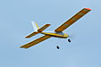
FlyingI was asked to test fly the model before crating and shipping it. It's been windy all year and I had my doubts as to being able to accomplish this. It wasn't until the end of the day that the wind calmed enough to risk flying the model and the wind was still a little stronger than I would have liked. The model handled the slight breeze (approx 5 mph) without difficulty. The elevator was a little touchy which I expected because it had a lot of throw. I set it up so that mechanically it had the least throw possible (inner hole on the servo arm and outer hole on the elevator horn). When I got back from the field I drilled a new hole in the servo arm to reduce the throw some more. There is no room in the elevator horn for a new hole. The ailerons were effective enough but needed more differential than I had built in. The instructions and plans indicate that a plywood servo arm should be made that will create differential. This arm is supposed to be glued to the servo arm. Most glues don't bond well to nylon so I didn't make the plywood arm. Instead I bent the aileron horns. After test flying I bent the horns a little more and moved the linkages to provide some more throw. The model is slow and gentle in the air and very easy to fly. Nothing happens very quickly which will make it a good trainer. I believe the rudder is more important than the ailerons but either way (or preferably having both) will work. The landing gear doesn't like our grass field very much. We landed the model twice. The first landing (seen in the video) wasn't perfect but the model shouldn't have flipped over. The second landing was picture perfect and the model still flipped over. That may happen on every grass field landing for the life of this model but it won't hurt anything as the model is so light and has so little inertia that I doubt anything will break. Overall I like the way the model flies and its finished appearance. I didn't think the kit was as well done as it could have been but it was good enough and aside from a couple easily corrected problems it goes together well and should last a long time.
|
|
|
|
|
|
|
|
|
Copyright © 2006 Paul K. Johnson
|
|


 maiden_flight.wmv
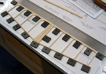 I
began construction building the tail surfaces and fuselage simultaneously. I made a few modifications to the
tail structure. The leading edge of the moving surfaces and trailing edges of the
fixed surfaces were replaced with 1/8” x 1/4” balsa to provide more surface area
for the hinges.
I
began construction building the tail surfaces and fuselage simultaneously. I made a few modifications to the
tail structure. The leading edge of the moving surfaces and trailing edges of the
fixed surfaces were replaced with 1/8” x 1/4” balsa to provide more surface area
for the hinges.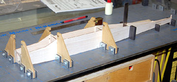 The fuselage construction and implementation bothered me. First, the two
sides are laser cut identically even though the right side needs to be cut shorter to create right
thrust. There is a line burned into both sides to show where the one fuselage side
is cut. It seems to me that if the manufacturer is going to do that why not
just cut each side to the correct shape in the first place?
The fuselage construction and implementation bothered me. First, the two
sides are laser cut identically even though the right side needs to be cut shorter to create right
thrust. There is a line burned into both sides to show where the one fuselage side
is cut. It seems to me that if the manufacturer is going to do that why not
just cut each side to the correct shape in the first place?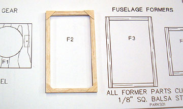 The formers are built from 1/8” square balsa. Ensuring they are square may be
a challenge for a beginning builder but with a little care and patience they
should be successful. I added 1/32" balsa gussets to the joints of all built-up
formers.
The formers are built from 1/8” square balsa. Ensuring they are square may be
a challenge for a beginning builder but with a little care and patience they
should be successful. I added 1/32" balsa gussets to the joints of all built-up
formers.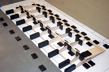 The wing is simple and everything fits well. However, I don’t like wood dowel
leading edges. I’ve always thought they were a bad idea. Dowels are never
straight and as you sight the leading edge you can always see dips and kinks in
the leading edge that will always be there.
The wing is simple and everything fits well. However, I don’t like wood dowel
leading edges. I’ve always thought they were a bad idea. Dowels are never
straight and as you sight the leading edge you can always see dips and kinks in
the leading edge that will always be there.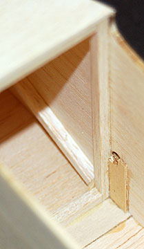 The landing gear design is something I probably never would have thought of
and if I did I probably would have decided against after about three minutes. Attaching it takes some finesse to avoid damaging the fuselage. The first time I
attached the gear, the rubber bands pulled the dowel down crushing the fuselage
sides. I quickly removed the gear to prevent further damage and added 1/32”
plywood supports inside the fuselage.
The landing gear design is something I probably never would have thought of
and if I did I probably would have decided against after about three minutes. Attaching it takes some finesse to avoid damaging the fuselage. The first time I
attached the gear, the rubber bands pulled the dowel down crushing the fuselage
sides. I quickly removed the gear to prevent further damage and added 1/32”
plywood supports inside the fuselage.